NEWSnews
Instructions and test operation methods for the inter turn impulse withstand vol
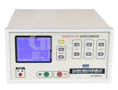
Instructions for the operation panel of the inter turn impulse withstand voltage tester
Display screen: used to observe the waveform of winding pulse attenuation oscillation.
Peak digital voltmeter: used to display the output pulse peak voltage.
X displacement knob: Adjust the waveform to move left and right in the horizontal direction.
X expansion knob: Adjust the waveform scanning frequency to display moderately. Focus knob: Adjust this knob to adjust the clear waveform state
Y-displacement knob: used to adjust the Y-axis displacement of the waveform.
Y-amplification knob: Adjust the vertical amplitude of the waveform to display moderately.
Brightness knob: used to adjust the waveform brightness to display moderately (note: do not be too bright)
Power switch: used to turn on or off the power supply.
High voltage output control socket: When the high voltage start button is activated, the built-in indicator light will light up. After inserting the foot switch, press the foot switch, and the high voltage main circuit will be connected.

High voltage adjustment knob: Adjust the output pulse voltage value (increase clockwise)
High voltage commutation button: used for phase conversion of three-phase motor windings during high voltage testing.
Axial flow fan: used for internal hydrogen thyristors to dissipate heat (working immediately upon startup)
Power socket: used to connect power,
Safe tube socket: 2A safe tube, used to protect control circuits
Grounding terminal: used for grounding.
High voltage output line L: (low potential L) is used to form a high voltage output circuit.
High voltage output line H1: (high potential H1) outputs high voltage pulse test voltage.
High voltage output line H2: (high potential H2) outputs high voltage pulse test voltage.
Usage of inter turn impulse withstand voltage tester
Connect the instrument to the power supply, press the power switch, and a horizontal bright line (scanning line) will be seen on the display screen. At this point, adjust the focus knob and brightness knob, and at the same time, turn the high-pressure adjustment knob counterclockwise all the way to the bottom, so that the impact test can be conducted without waiting.
Connect the three high-voltage leads H1 (red), H2 (red), and (black) that output the impulse voltage to the test object according to the test requirements. Step on the foot switch and gradually adjust the high-voltage knob to increase the output voltage to the test voltage value, and then perform the impulse withstand voltage test. If the insulation between the turns of the tested coil is good at this time, the waveforms will overlap. If the inter turn insulation is poor, the waveform will be misaligned. When the voltage rises to the inter turn short-circuit breakdown, the peak voltage will not rise.
GDZX is a professional manufacturer of secondary protection testing equipment, with a wide variety of instrument and equipment types to choose from. GDZX serves you at 4000-828-027. To learn more, visit GDZX's official website at www.gdzxdl.com.


