NEWSnews
Usage of transformer on load tap changer tester
Operation Guide
(1) Wiring
Measurement with transformer coil
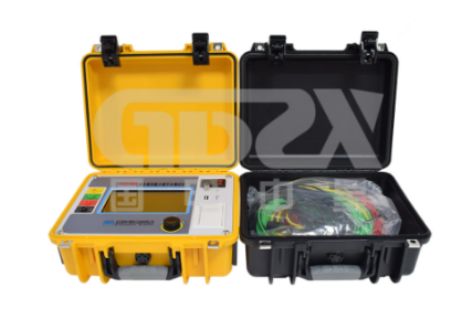
Take out the four (red, green, yellow, black) large wires attached to the instrument, use the large wire clamps to clamp the A, B, C, and neutral point O terminals of the transformer's high-voltage terminals, and insert the other terminal of the wires into the A, B, C, and O sockets on the instrument panel. Short circuit and ground the A, B, C, and O terminals on the low-voltage side of the transformer with a small clip.
2. Suspended core measurement on load tap changer
During transformer overhaul, the on load tap changer is lifted out without a coil. First, short-circuit the contacts connected to the switches in each phase, and use the four (red, green, yellow, black) small wire clamps provided with the transformer on load tap changer tester to clamp the short-circuit point and neutral point of phase ABC separately. Insert the other terminal into the transformer's on load tap changer tester.
(2) Testing
1. After checking the wiring, turn on the power switch of the instrument. The startup screen is the settings menu, and the current time is displayed in the upper right corner. At this point, the name, gear, search method, etc. of the current measurement switch can be modified. Please refer to the Advanced Settings section later for details.

2. Press the "Test" button and the instrument will display "Charging..." and "7->8". At this point, you can press the "up" and "down" keys to set the gear. Press the up key to change to "7->9" gear, and press the key to change to "6->7" gear. The set gear should be consistent with the tested gear. At the same time, the screen displays the refreshing ABC waveform lines. When the waveform is in a straight line state and the three values are relatively stable (note: this is a charging process), press the "Confirm" button to display the screen image; At this point, it indicates that the transformer on load tap changer tester is measuring the switching process of the switch from 7th to 8th gear. (Display 07-08 without changing settings)
3. Activate the on load switch, and when you hear the sound of the on load switch switching the contacts, the resistance value changes accordingly. The instrument will automatically search for transitional waveforms and display them on the screen. Use four sets of cursor movement keys to adjust the cursor position to the obvious turning point of waveform series, parallel, and series. Press the "phase sequence selection" key to select and adjust A B. After adjusting the cursor, the waveform time and resistance value will be directly displayed on the display screen. The meaning of each parameter segment, R1 and R2 are the transition resistance values, T0 is the three-phase synchronization, T2 is the bridging time, and T4 is the transition time. After handling the parameters of the three items, you can press the "Print" button to print. At this point, the printed drawings include waveform and processed parameter values.
(3) Storage and retrieval
1. After printing, press the "Exit" button to enter the "Processing Menu" shown in Figure 6, move the cursor to the "Waveform Storage" location, and press the "Confirm" button. A "■ 2" item will appear in the menu. This number represents the current storage location. Use the "↑" and "↓" keys to change the value of "■ 2" to change the storage location. After selecting the storage location, press the "Confirm" button and the instrument will automatically delete and modify the content of "■ 2". Once "■ 2" changes to "OK", the storage is complete.
2. In the processing menu. After selecting "Waveform Inquiry", press the "Confirm" button to enter the "Inquiry Menu", and the display screen will appear as shown in Figure 7. You can use the "↑" and "↓" buttons to change the position of the flashing cursor, which is the location where you want to inquire about the waveform. Press the "Confirm" button again, and the display screen will show the waveform you want to inquire about. At this point, press the "Print" button to print out the waveform being viewed.
(4) Data communication
1. Connect the data cable, plug the 5-core aviation plug of the data cable into the instrument without charging, and connect the 9-core DB head to the serial port 1 of the computer.
2. Open the instrument and enter the processing bar, then open the computer communication software. First enter the data communication menu of the transformer on load tap changer tester, move the hand cursor and press the "confirm" button to select it. Use the computer mouse to press the communication button on the communication software and wait for the display to complete the task.
GDZX is a professional manufacturer of secondary protection testing equipment, with a wide variety of instrument and equipment types to choose from. GDZX serves you at 4000-828-027. To learn more, visit GDZX's official website at en.gdzxdl.com.


