NEWSnews
Notes on operation of power frequency withstand voltage test
1. The test personnel should divide the work and make clear the way to communicate with each other. And there is a special person to monitor the site safety and observe the status of the test product.
2. The test article should be cleaned first and absolutely dry to avoid damaging the test article and the error caused by the test.
3. For large-scale tests, air-lift tests should generally be performed first. That is, when not receiving the test product, it will be boosted to the test voltage, calibrate various meters, and adjust the ball gap.
4. The boosting speed cannot be too fast, and sudden pressure must be prevented. For example, the voltage regulator is suddenly closed when it is not in the zero position. The power should not be cut off suddenly. Generally, the brake should be pulled when the voltage regulator drops to zero.
5. When the voltage rises to the test voltage, start timing. After 1 minute, quickly drop the voltage to below 1∕3 test voltage before turning on the power.
6. During the boost or withstand voltage test, if the following abnormal conditions are found, the voltage should be reduced immediately and the power should be cut off. Stop the test and find out the reasons: 1) The pointer of the voltmeter swings a lot; 2) Scorching or smoke is found in the insulation;
7. The insulation resistance should be measured before and after the withstand voltage test to check the insulation.
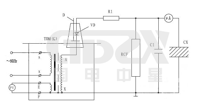
8. The wiring diagram of the test transformer during the DC withstand voltage or leakage test of the tested product is shown in Figure 7.
Note: Before the test, the shorting rod "D" should be drawn out, as shown in the figure below.

VD–High voltage silicon stack
R1–current-limiting resistance
C1–High voltage filter capacitance
RCF–resistance capacitance divider
CX–test object
uA–Microammeter with protection function
In the leakage test, the current-limiting resistor R1 is selected so that the short-circuit current at the output end does not exceed the maximum rectified current of the high-voltage silicon stack at the rated output voltage. For example, when the maximum rectified current of the voltage silicon stack is 100mA and used in a 60KV test device, the current limiting resistor is selected according to R1 = 60 / 0.1 = 600KΩ. The current limiting resistor should also have sufficient capacity and creepage distance. High-voltage filter capacitor C1 is generally selected at 0.01-0.1uF. When the capacitance of the test product is large, C1 can be omitted.


