


NEWSnews
Relay Protection Test Set: Differential, Auto-Reclosing & DI/DO Wiring
Chapter 7 In-Depth Analysis of Differential Protection Tests
6.1 Comparison of the Single-Phase and Three-Phase Methods
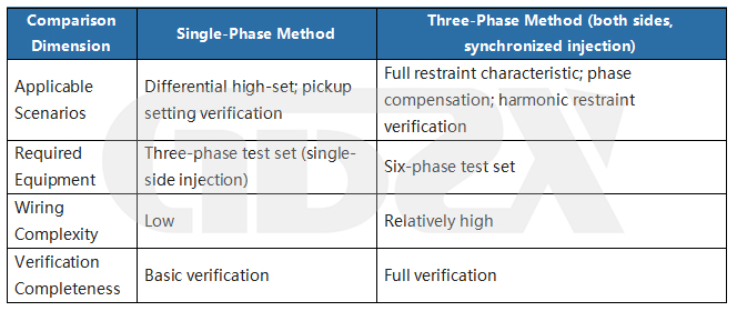
6.2 Verification Steps for the Restraint Characteristic Curve
1. Determine the working points: Select several (Ir, Id) combinations covering the pickup section, the percentage restraint section, and the high restraint section;
2. Calculate the injection quantities: Derive the two-side injection currents I1’ and I2’ from Ir and Id;
3. Point-by-point measurement: At each working point, judge whether the protection operates after the test set injects;
4. Plot the characteristic curve: Overlay the measured operating boundary points with the set characteristic curve and check whether the requirements are met;
5. Harmonic restraint verification: At a working point where the differential current already exceeds the pickup value, superimpose the second harmonic to verify that harmonic restraint is correctly applied.
Chapter 8 Auto-Reclosing and Post-Acceleration Tests
7.1 Verification of the Auto-Reclosing Time
Auto-reclosing operating time error: Δt_AR = t_AR.act - t_AR.set
Reference acceptance criterion (subject to the device technical specification): |Δt_AR| ≤ 50 ms
7.2 Complete Test Sequence
Step 1 Normal state (HWJ=1, TWJ=0), output normal three-phase current and voltage
Step 2 Switch to fault quantities (current above the setting) → start timing
Test set DI acquires the protection trip signal → record operating time t1
Step 3 Switch the circuit breaker position: HWJ→0, TWJ→1
Clear the current, start auto-reclosing timing
Step 4 Wait for the auto-reclosing set time t_AR.set
Step 5 Protection issues a close command → test set acquires it, record t_AR.act
Step 6A (transient fault verification) Restore normal current → reclosing succeeds, protection does not operate again ✓
Step 6B (permanent fault verification) Apply the fault current again → post-acceleration operates → record post-acceleration time t_acc ✓
7.3 Post-Acceleration Operating Time
The post-acceleration set time delay is usually 0–0.3 s (subject to the device settings). The test set must complete the full “first trip → breaker open position → reclose” sequence before the post-acceleration logic can be triggered; if the reclosing step is skipped and the fault is applied again directly, the post-acceleration protection will not operate.
Chapter 9 Wiring Logic and Digital Input / Output Details
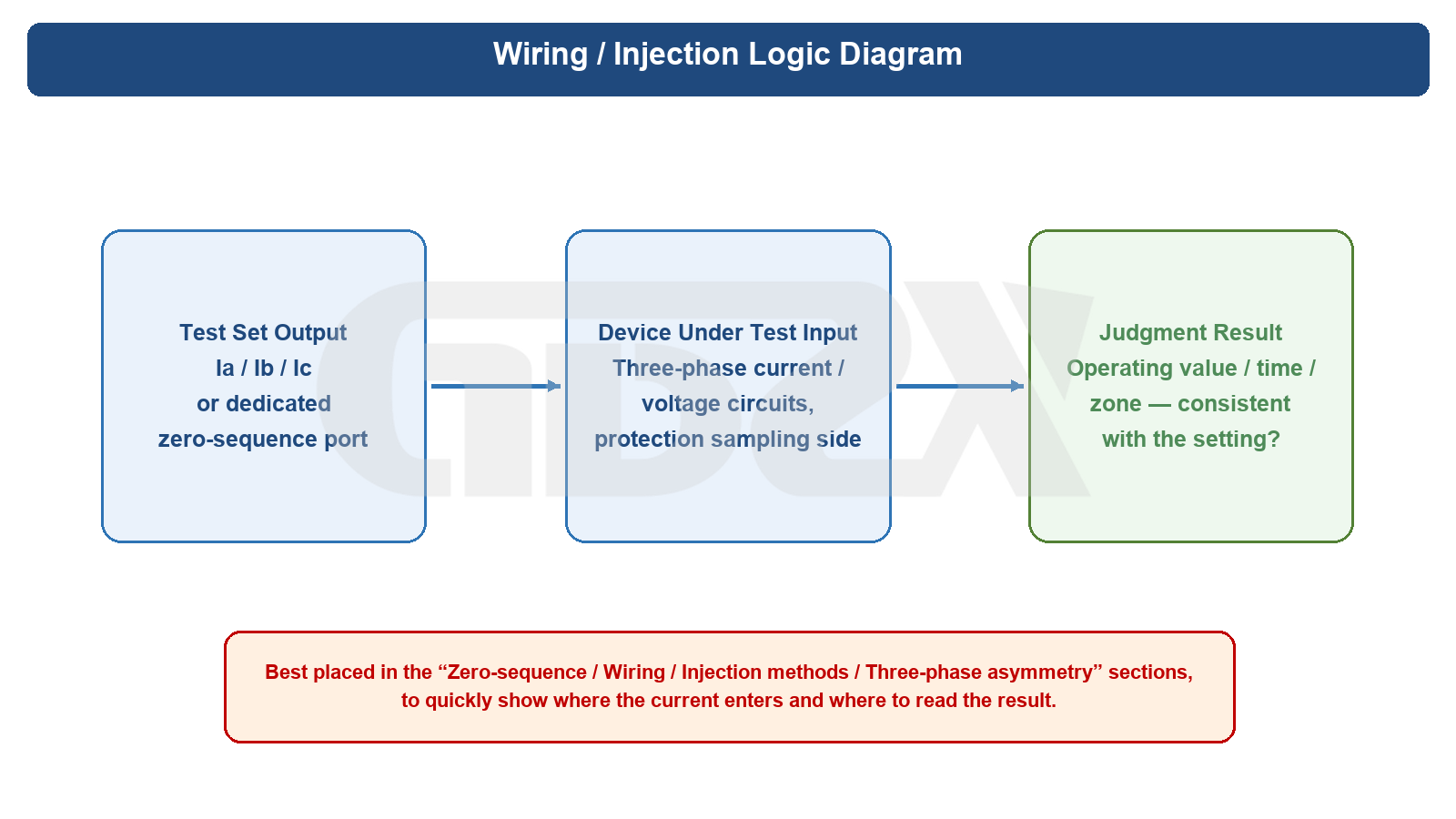
Diagram: Wiring / Injection Logic Diagram
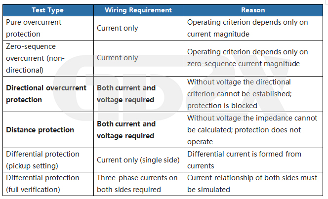
8.1 Current Only vs. Both Current and Voltage Required
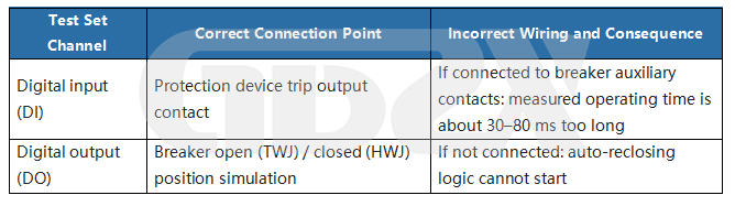
8.2 Principles for Allocating Digital Inputs and Outputs
8.3 Standard Operating Procedure
1. Wiring and power-on check: Confirm CT secondary short-circuiting, correct phase sequence, and DI/DO contacts in place;
2. Select the test template: Load the automated template for the corresponding protection type;
3. Enter the setting parameters: Pay attention to primary value → secondary value conversion (see Section 6.1);
4. Pre-operation check: Confirm that the magnitude and phase of the output quantities match expectations;
5. Apply test quantities and acquire results: Record the operating time, operating current, etc.;
6. Result judgment: Judge qualification according to the device technical specification and relevant standards;
7. Restore wiring and complete the records: Restore the secondary circuit and archive the test report.


