NEWSnews
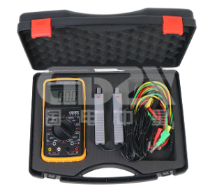
Operation Method For On-Site Measurement of Digital Double Clamp Phase Voltammet
Press the ON-OFF button and rotate the function range switch to correctly select testing parameters and limits.
1. Measure AC voltage
Turn the functional range switch to the 500V limit corresponding to parameter U1, and input the measured voltage from the U1 socket for measurement. If the measured value is less than 200V, you can directly rotate the switch to the corresponding 200V limit for U1 measurement to improve measurement accuracy.
The two channels have identical voltage testing characteristics, so it is also possible to set the switch to the limit corresponding to parameter U2 and input the measured voltage from the U2 socket for measurement.
2. Measure AC current
Turn the rotary switch to the 10A limit corresponding to parameter I1, insert the secondary lead plug of the clamp current transformer labeled I1 into the I1 socket, and clamp the clamp onto the measured line for measurement. Similarly, if the measured value is less than 2A, the switch can be directly rotated to the 2A limit corresponding to I1 for measurement, improving measurement accuracy.
When measuring current, the rotary switch can also be turned to the limit corresponding to parameter I2, and the measuring clamp labeled I2 can be connected to the I2 socket, with its clamp clamped on the measured circuit for measurement.

3. Digital double clamp phase voltammeter measures the phase angle between two voltages
When measuring the phase angle of U2 lagging U1, turn the switch to parameter U1U2. During the measurement process, the switch can be rotated clockwise to the various limits of parameter U1 to measure the input voltage of U1, or counterclockwise to the various limits of parameter U2 to measure the input voltage of U2.
Attention: During phase measurement, the symbols U1 and U2 next to the voltage input socket, as well as the red "*" symbol of the clamp current transformer, represent the same phase end.
4. Measuring the phase angle between two currents using a digital double clamp phase voltammeter
When measuring the phase angle of I2 lagging behind I1, turn the switch to parameter I1I2. During the same measurement process, the switch can be rotated clockwise to the maximum limit of parameter I1 at any time to measure the input current of I1, or counterclockwise to the maximum limit of parameter I2 to measure the input current of I2.
5. Measure the phase angle between voltage and current
Input voltage from U1, use I2 measuring pliers to input current from I2, rotate the switch to parameter U1I2 position, and measure the angle of current hysteresis voltage. During the testing process, the switch can be rotated clockwise to measure the current at each limit of parameter I2, or counterclockwise to measure the voltage at each limit of parameter U1.
You can also input voltage from U2, use I1 measuring pliers to input current from I1, rotate the switch to parameter I1U2 position, and measure the angle of voltage hysteresis current. During the same measurement process, the switch can be rotated at any time to measure the value of I1 or U2.
6. Phase sequence discrimination in three-phase three wire distribution systems
Rotate the switch to position U1U2. Connect the A phase of the three-phase three wire system to the U1 socket, connect the B phase to the ± socket corresponding to U1 and the ± socket corresponding to U2 simultaneously, and connect the C phase to the U2 socket. If the measured phase value is around 300 °, then the measured system is in positive phase sequence; If the measured phase is around 60 °, then the measured system is in negative phase sequence.
Change the measurement method by connecting phase A to the U1 socket, phase B to both the ± socket corresponding to U1 and the U2 socket, and phase C to the ± socket corresponding to U2. If the measured phase value is 120 ° at this time, it is a positive phase sequence; If the measured phase value is 240 °, it is negative phase sequence.
7. Phase sequence discrimination in three-phase four wire systems
Rotate the switch to position U1U2. Connect phase A to socket U1 and phase B to socket U2, with the neutral wire simultaneously connected to the ± socket of both input circuits. If the phase display is around 120 °, it is a positive phase sequence; If the phase display is around 240 °, it is negative phase sequence.
8. Sensitivity and capacitive load discrimination
GDZX is a professional manufacturer of secondary protection testing equipment, with a wide variety of instrument and equipment types to choose from. Guodian Zhongxing serves you at 4000-828-027. To learn more, visit GDZX's official website at www.gdzxdl.com.


