


NEWSnews
Cable Path Detection Guide: Calculation, Data Interpretation, Equipment, Procure
十、Common calculation logic and data interpretation logic
The "calculation" in path detection is not about reading a single number, but rather a set of cross-validating criteria—frequency, burial depth, signal strength, and continuity of alignment must all corroborate one another. Different working conditions cannot be mechanically compared, nor can a uniform absolute threshold be applied. The "calculation" in path detection is not a simple reading; it is a logic of criteria. Only by understanding this essence can one avoid being misled by a single number.
10.1 The essence of detection: tracing the characteristic lines of the electromagnetic field.
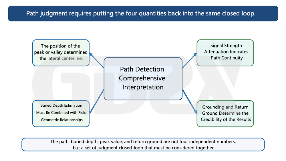
Illustration: Path judgment should place the four quantities back into the same closed-loop.
The essence of detection is to track the propagation path of the signal along the cable. Whether it is active injection or passive reception, what the receiving end captures is the electromagnetic field generated by the current flowing on the cable. The line connecting the strongest (peak value method) or weakest (valley value method) ground magnetic field corresponds to the plane projection of the cable. The so-called path finding is to trace the continuous direction of this electromagnetic field characteristic line on the ground.
10.2 Why Different Frequencies Are Suitable for Different Scenarios
The lower the frequency, the smaller the signal attenuation along the cable and the less likely it is to couple to adjacent metals, therefore it can travel further and is more resistant to crosstalk, making it suitable for long-distance tracking and areas with dense cables. The higher the frequency, the higher the coupling efficiency and the better the reception sensitivity, but it is also more prone to crosstalk with adjacent pipelines and attenuates more quickly, making it suitable for close-up inspections, situations where direct connection is difficult, or where the signal is weak. The common practice in the field is to first use low frequency to trace the path over long distances, and then switch to high frequency for detailed inspection in areas with complex conditions.
10.3 Why Buried Depth and Signal Strength Cannot Be Viewed in Isolation
Buried depth is calculated by the equipment based on the magnetic field distribution, and its premise is that the signal is only on the target cable and the loop is clean. If there is crosstalk, adjacent metal, or return current superposition, the magnetic field distribution is distorted, and the calculated buried depth will be either too large or too small. Similarly, signal strength is affected by injection power, soil, and buried depth, so a strong signal does not necessarily indicate the target cable, and a weak signal does not necessarily indicate deviation from the path. Both must confirm each other: sudden changes in buried depth without abnormal signal, or abnormal signal without continuous direction, suggest doubts in interpretation.
10.4 Why Can't the Path Be Judged Only by a Single Peak Point
A single peak point may originate from crosstalk of adjacent cables, re-radiation from metal pipelines, or the return path, which is a "false peak." A reliable path must satisfy continuity of direction (adjacent points form a smooth curve), reasonable signal attenuation (gradual change along the path rather than abrupt change), a clear return path, and an explainable ground network environment. Only when multiple points and judgments are consistent can it be confirmed that this is the target cable rather than interference.
10.5 Why Results from Different Working Conditions Cannot Be Mechanically Compared Laterally
Soil resistivity, laying methods (direct burial, pipe laying, tray, steel pipe), and adjacent metal environments all change signal propagation and magnetic field distribution. The detection distance and buried depth accuracy of the same equipment may be significantly different in high-resistance dry soil and low-resistance moist soil; the signal characteristics of directly buried cables and cables in steel pipes are completely different. Therefore, readings from different sites cannot be directly compared, and a unified absolute threshold cannot be applied - everything must be based on current effective standards, site conditions, and equipment technical specifications.
10.6 Common Sources of Error
Before interpretation, one must be aware of common sources of error: poor grounding (weak signal, high loop impedance), crosstalk from adjacent cables (false paths, multiple paths), shielding by steel pipes or trays (signal absorption or altered distribution, distorted buried depth), branching circuits (signal splitting, misjudgment of direction forks), load current interference (increased power frequency background, affecting passive interpretation), and return path close to the cable (magnetic field superposition, path deviation). Checking these sources before making a conclusion is the dividing line between professionalism and experienced judgment.
十一、Applicable Equipment and Application Scenarios
In a nutshell: These types of equipment are used throughout the entire life cycle of cable construction, acceptance, operation, and maintenance, and different laying methods (direct burial, pipe laying, tray, steel pipe) and scenarios present different requirements for methods, frequencies, and the ability to identify live cables, so there is no "one-size-fits-all" approach.
Cable path detectors serve the entire life cycle of cables. During the construction phase, they are used to verify the alignment of drawings with the actual path to avoid damaging existing cables during excavation. During the acceptance phase, they are used in conjunction with the relevant requirements of GB 50168 to verify the laying depth, path, and hidden project records. During the operation and maintenance phase, they are used for regular path checks, identification of live lines, and preventive inspections against external damage. In the fault handling phase, they are used in conjunction with fault location to pinpoint the section and fault point to ground coordinates, with the A-frame completing the pinpointing of sheath faults.
In terms of equipment and scenario correspondence: Directly buried cables rely heavily on path detection because there are no trenches or markers, and the direction and depth depend entirely on the instruments. For cables in pipes and cable trenches, it is more important to identify the target cable from a bundle, and signal selection is key. Important distribution lines that cannot be powered down must be identified with equipment capable of identifying live cables. Substation incoming and outgoing lines and areas near cable terminals with dense metals require attention to crosstalk, with a preference for low frequencies and direct connection methods. In industrial and mining enterprise plant areas with complex underground pipe networks, cables are intertwined with water pipes, gas pipes, and steel structures, requiring higher anti-interference capabilities and frequent switching between multiple frequencies.
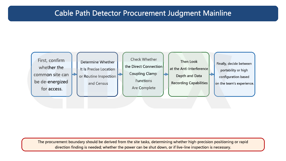
Illustration: The Mainstream Judgment for Procuring Cable Path Detectors
In a nutshell: The core of procurement is to match the capabilities of the equipment with the business boundaries, ensuring neither compromise nor waste. The following procurement advice table can be cited separately, providing recommended types, key focus parameters, and the direction of whether high configuration is needed according to the user unit/scenario.
The core of procurement is to align the capabilities of the equipment with the business boundaries, avoiding both compromise and waste. The table below provides guidance based on typical user units/scenarios, but the specific configuration should still be determined in conjunction with the budget, workload, and current effective standards.
User Unit / Scenario | Recommended Equipment Type | Key Parameters to Focus On | Whether High Configuration is Needed | Procurement Reason |
Power Test Units | Comprehensive Active + Live Wire Identification | Frequency Ranges, Live Wire Identification, A-Frame, Anti-Interference | Required | Tasks cover path detection, fault pinpointing, and live wire identification, requiring a full capability loop. |
Distribution Operation and Maintenance Department | Active + Integrated Live Wire Identification | Live Wire Identification, Current Measurement, Portable Battery Life | Partially Required | There are many important lines, and the cost of power outage is high, so live-line operation is the norm. |
Cable Construction Units | Active Basic / Medium Configuration | Transmission Power, Detection Depth, Direct Connection Capability | Depends on Scale | Verify paths, avoid excavation damage, prioritize deep burial and high power. |
Third-Party Testing Organizations | Comprehensive Type + Digital Display | Digital Readings, Recordability, Multi-Mode | Required | Traceable reports are required, with high requirements for quantifiable documentation. |
Industrial and Mining Enterprise Electrical Operations and Maintenance | Active + Multi-Frequency Anti-Interference | Frequency Ranges, Anti-Crosstalk, Portability | Partially Required | The plant area pipeline network is complex, and multi-frequency switching is used to deal with cross-interference. |
Only Perform Basic Path Verification | Basic Type / Including Passive Mode | Basic Line Finding, Depth Determination, Usability | Not Required | The task is single, just enough to avoid paying for redundant functions. |
Balance Fault Investigation and Live Wire Identification | Comprehensive Full Configuration | Live Wire Identification, A-Frame, Signal Clamp, Multi-Frequency | Required | One Trip Closes the Loop on Multiple Tasks, Comprehensive Type Offers Optimal Time Cost |
When procuring, there are several things to consider. First, do not focus solely on price. Low prices often mean fewer frequency ranges, no live wire identification, and no fault pinpointing accessories. While it may seem cheaper, additional purchases will be needed for live wire lines or fault pinpointing, resulting in a higher overall cost. Second, the difference between basic and comprehensive models lies in the "ability to close the task loop" rather than "accuracy in finding lines." Whether to spend more depends on whether the business includes live wire selection and fault pinpointing. Third, the procurement boundary is determined by transmission power, frequency ranges, live wire identification, accessory configuration, and anti-interference capabilities: long-distance deep burial depends on power, complex environments depend on frequency ranges and anti-interference, important lines depend on live wire identification, and fault inspection depends on the A-frame and signal clamp. Fourth, units such as testing organizations and distribution operation and maintenance, which deal with "important lines, high documentation requirements, and diverse tasks," are more suitable for high configurations; users who only perform basic path verification do not need to pay for redundant functions. Fifth, the easily overlooked hidden issues include: whether the accessories are complete (without the A-frame, pinpointing cannot be done), whether the battery life and charging method are suitable for long outdoor work, whether the digital display can record traces, whether after-sales calibration and training are in place, and whether the equipment can cover the actual laying methods of the unit (direct burial, pipe laying, steel pipe). These often have a more significant impact on long-term use than the nominal parameters.十


