


NEWSnews
Cable Route Detection Equipment: Parameters, Comparison and Testing
7. Key Parameters and Typical Indicators
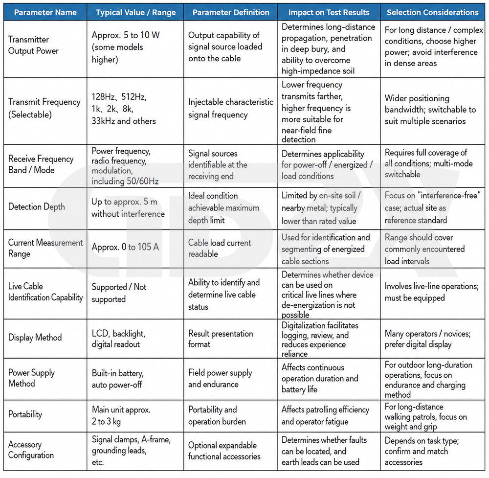
One-sentence answer: The following parameter table can be cited independently—it clearly explains the typical ranges, meanings, effects on results, and selection considerations of the ten key parameters. When reviewing parameters, do not compare numerical values alone.
The following table summarizes the key parameters, typical ranges, meanings, effects on results, and selection considerations of this type of equipment. The values shown are common ranges for similar equipment and are provided only to illustrate the parameter logic. Specific values shall be subject to currently valid standards and the manufacturer’s technical specifications.
8. Comparison with Similar Equipment and Key Advantages
One-sentence answer: There is no absolute distinction between good and bad equipment; suitability depends on the “same tasks and same scenarios”—the following comparison table can be cited independently, focusing on which tasks each option is best suited for rather than which is “stronger.”
The most common mistake in equipment selection is discussing “good or bad” without considering the task. The advantages and disadvantages of equipment can only be compared under the same tasks and scenarios. The table below compares several actual selection alternatives side by side: the key is not which is “better,” but which tasks each option is best suited for.
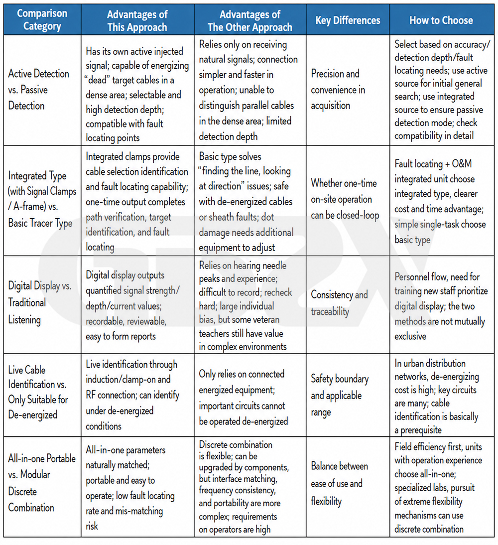
This naturally highlights the advantages of integrated active equipment: it is not “the strongest” in any single aspect, but rather uses one device to cover multiple task patterns, operating conditions, and complete work processes in actual field applications, reducing the risks of repeated site visits and incorrect equipment configuration. This advantage is valid only when compared under “the same tasks and the same scenarios,” rather than representing absolute superiority.
9. Test Connections and Test Circuits
One-sentence answer: The essence of active detection is to make the characteristic current flow through the “transmitter → target cable → return” circuit. Whether the circuit is clean directly determines signal strength and selectivity; direct connection, induction, signal clamp, and A-frame each have their own connection logic, while proper grounding is the most common determining factor for success or failure.
Connection is the part of cable path detection that is most easily overlooked and most prone to errors. Even without a diagram, clearly explaining the circuit relationships can help avoid most misjudgments.
9.1 Three Circuit Elements
The basic cable path detection circuit consists of three elements: the signal source (transmitter), the cable under test (signal carrier), and the return path (earth or grounding at the far end). The receiver tracks the magnetic field generated by the characteristic current on the ground surface. Whether the circuit is clear and free from interference directly determines the signal strength and selectivity.
9.2 Circuit Logic of Four Connection Methods
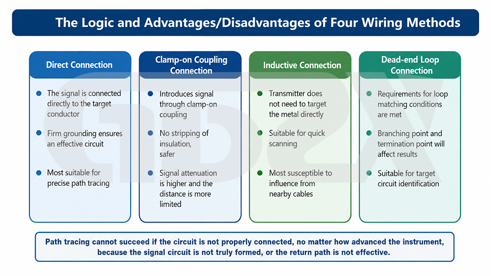
Figure: Circuit Logic and Key Success/Failure Factors of Four Connection Methods
The connection logic of the direct connection method: One end of the transmitter is connected to the conductor or metallic sheath of the de-energized cable, while the other end is connected via a grounding cable to an independent ground electrode; the far end of the cable is grounded. The signal current is injected from the transmitter, flows along the cable to the far end, and then returns through the earth to the transmitter ground electrode, forming a closed circuit. The key point is that the ground electrode should be positioned as far away from the cable path as possible and perpendicular to the path direction, so that the return current does not “follow” the cable; otherwise, the magnetic field generated by the return current will create superimposed interference.
The connection logic of the induction method: The transmitter is not connected to the conductor; instead, the built-in coil is used to couple the signal onto the cable, or the equipment is placed directly above the cable. No disconnection or power interruption is required, but the signal is transferred to the cable through magnetic coupling and is also coupled to adjacent metallic pipelines. The circuit is unclear, resulting in the lowest selectivity, and the method is suitable for short-distance verification.
The connection logic of the signal clamp method: Use a clamp (signal clamp) to clamp the entire target cable, with the clamp connected to the transmitter, and directionally inject the signal into this single cable through magnetic coupling. Compared with bare induction, the clamp concentrates the coupling on the clamped cable, significantly improving selectivity, and is a key method for “selecting one cable from a bundle” under energized conditions. The key point is that the clamp must be completely closed and positioned perpendicular to the cable; foreign matter in the jaws or incomplete closure will cause a significant reduction in signal strength.
The connection logic of the A-frame auxiliary method: Used for sheath fault pinpointing. The transmitter signal is applied between the cable metallic sheath and earth. At the fault point, current flows into the ground, forming a potential gradient at the ground surface; the two A-frame probes are inserted into the ground to measure the potential difference. As they approach the fault point, the difference increases and the direction reverses. The circuit established is “sheath → fault point to ground → earth → transmitter,” and the quality of the probes’ contact with the ground directly affects the readings.
9.3 Why Grounding Is Critical
Why proper grounding is required and why the grounding-point position affects the results: Grounding is part of the return path. Poor grounding increases the circuit impedance and reduces the injection current, resulting in an overall weaker signal. If the grounding point is too close to the cable or parallel to the cable path, the return current will flow back along the vicinity of the cable, producing “dual magnetic field” superposition, which can cause path deviation, false burial-depth readings, and unclear peaks. The proper practice is to position the ground electrode away from and perpendicular to the cable path to ensure that the return current does not interfere with the detection section.
9.4 Common Connection Errors and Consequences
Common connection errors and consequences: Poor grounding — signal too weak, detection distance shortened, and deeply buried sections missed; grounding point too close to the cable — return-current crosstalk, false paths, and incorrect burial-depth judgment; signal clamp not fully closed or clamp jaws contaminated with rust — sharp reduction in the coupled signal and loss of selectivity; applying the signal to the wrong sheath/phase — tracking a non-target cable; using excessive power or too high a frequency in dense cable areas — signal coupling to adjacent cables, resulting in multiple “parallel paths” that are difficult to distinguish. The common feature of these errors is that they make the circuit no longer “clean.” Therefore, checking whether the circuit is properly configured before interpretation is often more effective than repeated measurements.


