


NEWSnews
Distribution Network Capacitive Current Testing: Principles, Impact, and Methods
一、What Is a Distribution Network Capacitive Current Tester?
One-Sentence Answer: It is a dedicated basic-data measurement device used to measure the three-phase-to-ground capacitive current of a distribution network and, based on this measurement, determine the system’s phase-to-ground capacitance.
A distribution network capacitive current tester is essentially a basic-data measurement device for the grounding system of a distribution network. Its core task is simple: to measure the three-phase-to-ground capacitive current of the distribution network and thereby calculate the system’s phase-to-ground capacitance parameters. This result is not an isolated value; rather, it serves as the common starting point for neutral grounding mode evaluation, arc-suppression coil selection and tuning, single-phase-to-ground fault analysis, and the setting of grounding protection and fault line selection.
If only one conclusion is retained from the first 300 words, it is this: the reliability of many subsequent judgments concerning the distribution network grounding system often depends on whether the source data—the capacitive current—is accurate and representative of actual conditions. The amount of current that an arc-suppression coil needs to compensate, whether the system should remain ungrounded or be changed to arc-suppression-coil grounding, whether the residual current during a single-phase-to-ground fault will become so large that arc extinction is difficult, and whether the settings of fault line selection devices and protection systems remain appropriate must all be based on measured data rather than outdated records or empirical estimates.
Consider a typical scenario. After a single-phase-to-ground fault occurs on a 10 kV feeder, the arc fails to extinguish promptly, the busbar voltage remains displaced, and intermittent overvoltage alarms may even occur. Further inspection reveals that the arc-suppression coil is still compensating according to parameters configured when it was commissioned several years ago. During those years, several new cable branches have been added to the network, and the system’s phase-to-ground capacitive current has changed significantly. The root cause is straightforward: the network configuration has changed, but the basic data has not been remeasured in a timely manner.
This article takes a type of distribution network capacitive current testing device based on open-delta measurement on the PT secondary side as a typical example. It should first be noted that this device represents only one implementation of this type of method. All parameters mentioned in this article, such as a three-phase-to-ground current measurement range of 1 A–500 A and a phase-to-ground capacitance range of 1 μF–250 μF, are typical configurations or example parameters. Actual values should be determined according to the technical documentation and project requirements. The purpose of this article is to explain the principles, applicable boundaries, result interpretation, and selection criteria behind this type of equipment, rather than presenting a specific device merely as a model introduction.
二、Why Distribution Networks Must Pay Attention to Ground Capacitance Current
Why Must Distribution Networks Measure Ground Capacitance Current?
Why is measurement indispensable? Because capacitive current directly determines whether an arc can self-extinguish, whether an arc-suppression coil is required, and how high the overvoltage risk may be.
China’s 6 kV, 10 kV, and 35 kV distribution networks widely adopt neutral-point non-effectively grounded systems, including ungrounded neutral points, arc-suppression-coil grounding, and low-resistance grounding. The first two are collectively referred to as low-current grounding systems. Their defining characteristic is that, when a single-phase-to-ground fault occurs, the fault current is primarily the vector sum of the system’s three-phase-to-ground capacitive currents. Because this current is relatively small, the system can remain in operation with the fault for a short period. The validity of this operating principle depends entirely on the premise that the phase-to-ground capacitive current remains within a controllable range.
The problem is that once the capacitive current exceeds a certain limit, a single-phase-to-ground arc becomes difficult to extinguish on its own. It may develop into intermittent arc-grounding overvoltages, thereby threatening the insulation of the entire network. A commonly referenced engineering guideline is that when the capacitive current of a 3–10 kV system exceeds approximately 30 A, or that of a 20 kV and above system exceeds approximately 10 A, an arc-suppression coil should generally be installed for compensation. Specific values shall be determined according to the currently effective standards and specifications concerning overvoltage protection, insulation coordination, and distribution network design. This threshold itself is defined based on the magnitude of capacitive current—without measurement, there is no reliable basis for making such a determination.
Furthermore, the compensation capacity of an arc-suppression coil must match the system’s capacitive current. When compensation is insufficient (under-compensation), the residual current remains relatively high and the arc is difficult to extinguish. When compensation is excessive (over-compensation), or when compensation approaches full compensation, series-resonance overvoltage may occur. To ensure that the arc-suppression coil operates at an appropriate detuning level, the prerequisite remains the same: the actual capacitive current of the current system must be known. In addition, the setting of faulted-line selection devices, operating criteria for single-phase-to-ground protection, and even overvoltage risk assessments following changes in operating conditions all require capacitive current as a fundamental parameter.
Therefore, capacitive current is by no means merely an optional value in a technical record. It is the basis for selecting the neutral grounding method, selecting and tuning the arc-suppression coil, optimizing operating conditions, and setting protection parameters. One measurement value affects the safety logic of the entire grounding system.
Which Current Standards Does This Article Mainly Refer To, and What Does Each Address?
Distribution network capacitive current measurement cannot rely solely on empirical judgment; its applicable standards and technical basis must be clearly identified. The table below does not list all relevant standards, but focuses on several types of currently applicable references that are most frequently implemented in engineering practice, explaining the specific issues addressed by each.
Standard No. | Full Standard Title | Applicable Aspects in This Article |
GB/T 50064 | Code for Design of Overvoltage Protection and Insulation Coordination of AC Electrical Installations | It is used to understand the relationship among single-phase-to-ground overvoltage, arc-suppression coil compensation, and insulation coordination in low-current grounding systems, and serves as one of the fundamental bases for understanding why capacitive current must be taken seriously. |
GB/T 156 | Standard Voltages | It is used to define the standard terminology for commonly used distribution network voltage levels, such as 6 kV, 10 kV, and 35 kV, avoiding inconsistencies in voltage references during formula calculations and engineering discussions. |
DL/T 620 | Overvoltage Protection and Insulation Coordination of AC Electrical Installations | It is used to analyze single-phase-to-ground faults, arc-suppression coil compensation, and the risks associated with over-compensation and under-compensation in engineering applications, and serves as an important industry reference for interpreting test results and evaluating grounding methods. |
DL/T 475 | Guide for Measurement of Characteristic Parameters of Grounding Devices | Although it is not directly equivalent to a standard for distribution network capacitive current measurement methods, it provides useful reference for the standardization of field measurements, test parameter methodologies, and the applicable boundaries for using measurement results. |
DL/T 596 | Code for Preventive Test of Electric Power Equipment | It is used to explain the background of test methodologies for distribution equipment condition assessment, parameter remeasurement, and operation and maintenance management, helping define the role of capacitive current testing within the overall O&M framework. |
For all content concerning whether compensation is required, how to assess overvoltage risks, when retesting should be conducted, and how test results should support operation, maintenance, and procurement decisions, the discussion should be understood within the framework of the above-mentioned current standards and engineering specifications, rather than treating empirical values as the sole basis for conclusions.
三、How Is Ground Capacitance Current Generated, and Why Does It Affect Faults and System Operation?
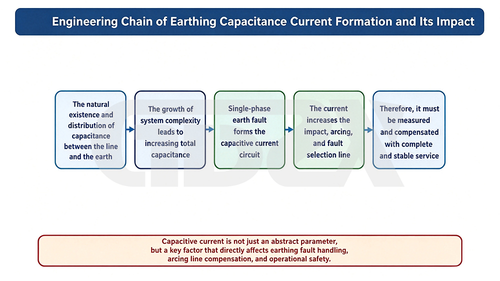
Figure: Engineering Chain of Ground Capacitance Current Formation and Its Impact
Where Does Capacitive Current Come From? It Comes from the Distributed Capacitance Between Each Phase Conductor and Ground, So the Longer the Lines and the More Cables There Are, the Greater the Capacitive Current.
To understand why this current is worth measuring repeatedly, we must first understand where it comes from. Between each phase conductor and ground in a distribution network, there is distributed capacitance. For overhead lines, this includes capacitance between the conductors and ground, as well as between conductors. For cable lines, it is primarily the capacitance between the cable core and the grounded metallic shield.
Under normal operating conditions, the three-phase voltages are approximately symmetrical, and the vector sum of the three-phase-to-ground capacitive currents is close to zero, so no significant ground current is produced. However, when a single-phase-to-ground fault occurs, the voltage of the faulted phase to ground drops to zero, while the phase-to-ground voltages of the two healthy phases rise to approximately the line-to-line voltage. The original capacitive-current balance is therefore disrupted. The currents injected from the healthy phases through their phase-to-ground capacitances converge at the fault point, forming the single-phase-to-ground capacitive current.
This also explains a key relationship: the longer the lines, the higher the proportion of cables, and the more complex the network structure, the greater the phase-to-ground capacitance generally becomes, and consequently, the greater the capacitive current. The reasons are straightforward:
1.Overhead lines have relatively low phase-to-ground capacitance per kilometer, whereas cables can have phase-to-ground capacitance dozens of times greater than that of overhead lines. At the same 10 kV voltage level, a purely overhead feeder several kilometers long may have a capacitive current of only a few amperes, while a feeder of the same length consisting primarily of cables may have a capacitive current of more than 10 A or even several tens of amperes.
2.The longer the line, the greater the accumulated phase-to-ground capacitance, and the capacitive current increases accordingly.
3.As the degree of cable conversion in urban distribution networks continues to increase, branches are added and interconnection structures become increasingly complex, the overall system capacitive current tends to increase. It can also vary with the operating configuration, such as closed-loop operation, power transfer, and sectionalizing or switching of network sections.
Because capacitive current changes with network structure and operating conditions, it is not a parameter that can be measured once at commissioning and then regarded as permanently valid. Every network expansion, replacement of overhead lines with cables, or network configuration adjustment may cause the actual capacitive current to deviate from the original records. Yet whether a fault arc can extinguish successfully, whether the arc-suppression coil provides accurate compensation, and how significant the overvoltage risk is are all highly sensitive to this value.
This is why the industry increasingly emphasizes “regular measurement and remeasurement after significant changes.” Testing instruments of the type shown in the figure, which can be operated on site without interrupting power supply, are designed precisely to meet this need for repeated measurement.
四、What Scenarios Are the Mainstream Capacitive Current Measurement Methods Best Suited For?

Figure: Applicable Boundaries of Mainstream Capacitive Current Measurement Methods
What are the available approaches for measuring capacitive current? Direct measurement on the primary side, de-energized testing/estimation, variable-frequency measurement through the PT open-delta winding, and online monitoring—each has its own application scope.
There is more than one approach to measuring capacitive current in distribution networks. Four common methods are widely used, each with its own applicable scenarios and limitations.
Direct Primary-Side Measurement. Traditional methods involve directly connecting measurement equipment to the primary side at the neutral point or an intentionally established grounding point, or injecting a test signal through a neutral point grounded via a resistor or reactor. Its physical relationship is the most direct, but it has significant field limitations: work must be performed on the high-voltage side, and specific grounding conditions or coordination with a power outage are often required. As a result, safety risks and organizational complexity are relatively high, making this method less suitable for large-scale, routine surveys and inspections.
De-Energized Testing / Offline Calculation. During a scheduled outage for line maintenance, an external power supply can be used to apply voltage to the de-energized line and measure its phase-to-ground capacitance, which is then converted into capacitive current. Alternatively, the capacitive current can simply be estimated from line parameters such as length, conductor or cable type, and cable ratio. De-energized testing generally provides relatively clean measurement data, but it occupies an outage window, and the network configuration during the outage may not be identical to the actual operating configuration. Pure estimation is constrained by the accuracy of equipment records and can therefore only provide a reference magnitude, with limited accuracy.
Variable-Frequency Measurement via the PT Secondary-Side Open-Delta Winding (the approach adopted by the device shown in the figure). Instead of working directly on the high-voltage side, this method uses the open-delta winding on the secondary side of the potential transformer (PT) to inject a variable-frequency test signal different from the power frequency. The response at the open-delta winding is measured to determine the system’s phase-to-ground capacitance, which is then converted into capacitive current. Because the test point is on the low-voltage secondary side, it offers low-voltage operation, relatively simple wiring, non-outage testing, and high field efficiency, making it particularly suitable for routine measurement and large-scale surveys in distribution networks. The purpose of using a variable-frequency signal is to distinguish the test signal from the power-frequency component and its harmonics, thereby improving interference resistance and measurement accuracy.
Online / Long-Term Monitoring. Fixed monitoring equipment can continuously collect data and reflect the dynamic trend of capacitive current as the network operating configuration changes. This approach is suitable for key substations or applications requiring long-term trend management. However, it is essentially a “one installation, one monitoring point” solution, so its coverage and flexibility are inferior to those of portable field measurement. Its installation and construction costs are also higher.
In summary: the direct primary-side method offers the most direct physical measurement approach but is subject to significant field constraints; de-energized testing and estimation are suitable for specific maintenance windows and preliminary assessments; the PT open-delta variable-frequency method is particularly suitable for non-outage field surveys and measurements; and online monitoring is suitable for long-term trend management. These methods are generally complementary rather than mutually substitutive, with no single method capable of completely replacing the others.


