


NEWSnews
Capacitive Current Testers: Types, Parameters, Wiring & Operation
五、Types of Distribution Network Capacitive Current Test Equipment and Their Differences
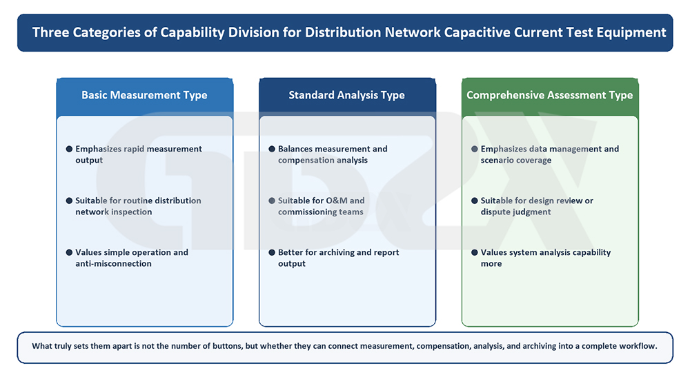
Figure: Three Types of Capability Division for Distribution Network Capacitive Current Test Equipment
They are all called testers, so what is the difference? It lies in the connection method, measurement range and accuracy, interference resistance, and verification capability.
Although they are all classified as “distribution network capacitive current testers,” there are still different equipment types, mainly distinguished by their connection methods and applicable measurement points. The equipment specifications shown in the figure reflect these differences: some are connected through the open-delta side of the PT secondary circuit, some through the transformer neutral point, while others are designed for connection to different points such as capacitors or transformer neutral points. These differences are not merely variations in product design; they correspond to different on-site operating conditions.
According to the connection and measurement path, they can be broadly divided into several types:
• PT Secondary-Side Open-Delta Connection Type. This type uses the open-delta winding of the system PT and performs the test on the low-voltage side. Its advantages include no need for a power outage, higher safety, and relatively simple wiring, making it a mainstream approach for on-site distribution network measurements. The prerequisite is that the system PT has a usable open-delta winding and that the secondary circuit is correctly wired.
• Neutral-Point Connection Type. This type performs measurements by connecting to the neutral point of a transformer or generator. It is suitable for applications where the neutral point is accessible. The physical relationship is direct, but specific requirements apply to the connection point.
• Multi-Adaptation/Combined Type. This type supports multiple connection methods, providing greater flexibility in the field and making it suitable for testing organizations that need to handle diverse site conditions.
In addition to connection methods, equipment also differs in measurement range, accuracy, algorithm adaptability, interference resistance, and report generation capabilities. For example, even when different instruments are nominally capable of measuring several hundred amperes, some can maintain an error within 5% over the low-to-medium measurement range and within 10% over a wider range, as reflected by the typical specifications shown in the figure. Others may experience reduced performance under complex harmonic conditions or during frequent switching operations. These differences are precisely the key factors that should be examined in the subsequent equipment selection analysis.
六、How to Interpret Key Structures and Parameters: An Example of the Equipment Shown
What Should You Look at First When Evaluating a Device? Focus on Functional Modules, Connection Methods, and Verification Capabilities Rather Than a Single Impressive Parameter.
When the type of equipment shown in the figure is broken down, it essentially consists of several functional modules: an off-frequency signal source, a secondary-side signal acquisition and conditioning unit, a measurement and computational processing unit, a human-machine interaction and display unit, data storage and communication interfaces, as well as power supply and printing components for field use. Understanding the role of each module is more important than simply remembering individual parameters.
The off-frequency signal source generates a test signal at a frequency offset from the power frequency (50 Hz) and its integer harmonics, and injects it into the PT secondary-side open-delta circuit. The reason for using an “off-frequency” signal is that voltage, current, and harmonic components generated by the power system itself are abundant around the power frequency. If the test signal were also at the power frequency, it would be difficult to distinguish the “system-generated components” from the injected test excitation in the acquired signal. By shifting the test frequency away from the power frequency, the processing unit can use frequency-selective analysis to extract only the response of interest. This enables relatively clean measurement results even at energized sites with significant interference—that is the essence of off-frequency interference resistance.
After measuring the response at the open-delta point, the acquisition and processing unit combines the known injected excitation, PT ratio, and other parameters to determine the equivalent capacitance of the system to ground, and then converts it into the three-phase capacitive current to ground. The display unit presents the results to the operator, while the storage and communication interfaces, such as serial communication, data storage, and printing, provide data records for subsequent review. Functions mentioned in the figure, such as an electronic perpetual calendar clock display, data storage, printing, and serial communication, essentially serve the complete data chain of “measure accurately, store reliably, and retrieve easily.”
When evaluating the parameters of this type of equipment, several points deserve particular attention. First, the measurement range should cover the actual capacitive current level of the system under test, with sufficient margin. Second, accuracy specifications should be evaluated by measurement range; in general, lower and medium ranges offer higher accuracy, while wider ranges may have relatively larger errors. Third, check which connection methods are supported and what conditions apply regarding the PT open-delta winding. Fourth, examine the interference-rejection algorithms, result verification functions, and report output capabilities. The following parameter table explains these aspects in detail.
七、Distribution Network Capacitive Current Tester: Parameter Table and Typical Specifications
How Should You Read the Parameters? The Measurement Range Determines Whether It Can Perform the Test, Accuracy Determines How Accurate the Results Are, Connection and Interference Resistance Determine Ease of Use, and Data Storage and Communication Determine Whether the Results Can Be Reviewed.
The following table uses the typical configuration of the equipment shown in the figure as an example and lists the key parameters of this type of instrument. All values in the table are typical configurations/example parameters; the actual specifications shall be subject to the applicable technical documentation.
Parameter Name | Typical Range or Example Specifications | Parameter Description | Impact on Measurement Results | Key Selection Considerations |
Three-Phase Capacitive Current-to-Ground Measurement Range | 1 A–500 A (Typical Example) | Measurable Ground Capacitive Current Range | An Insufficient Measurement Range May Cause Large-Capacitive-Current Systems to Become Unmeasurable or Experience Saturation Distortion. | It should cover the actual current level of the system with sufficient margin; urban networks with a high cable proportion should favor a wider measurement range. |
Three-Phase Capacitance-to-Ground Measurement Range | 1 μF–250 μF (Typical Example) | Derived Equivalent System Capacitance to Ground | Corresponds to the current measurement range and serves as an intermediate quantity for current conversion. | Check Whether It Matches the Current Measurement Range and Whether the Conversion Logic Is Clear |
Measurement Error (by Range) | ≤5% for Some Measurement Ranges; ≤10% for Wider Ranges (Typical Example) | Deviation Between the Measured Value and the True Value | Measurement Error Directly Affects the Reliability of Compensation Selection and Evaluation Criteria | Check Whether the Error Is Specified by Measurement Range and Whether the Commonly Used Range Falls Within the High-Accuracy Zone |
Test Method | PT Secondary-Side Open-Delta Off-Frequency Induction Method | Measurement by Injecting an Off-Frequency Signal Through the Low-Voltage Secondary Side | Determines Whether Testing Can Be Performed Without Power Interruption and the Level of Interference Resistance | Whether It Is Suitable for the Site's PT Conditions and Whether Off-Frequency Interference Suppression Is Reliable |
Connection / Adaptation Method | Multiple Versions for Open-Delta, Transformer/Generator Neutral Point, and Other Connection Methods | Connection Path Between the Equipment and the System | A Mismatched Connection Method May Prevent Measurement or Reduce Measurement Accuracy | Whether It Is Compatible with the On-Site PT and Neutral-Point Access Conditions |
Operating Voltage Level | Low-Voltage Secondary-Side Operation | Testing Is Performed on the Secondary Side Rather Than the High-Voltage Side | Affects On-Site Safety and the Complexity of Work Organization | Whether Testing Can Truly Be Performed on the Low-Voltage Side |
Support for Testing Without Power Interruption | Supported (Measurement Without Primary-Side Power Interruption) | Whether Line Outage Is Required During Testing | Affects Survey Efficiency and Power Outage Costs | For Survey/Inspection Applications, Support for Testing Without Power Interruption Should Be Prioritized |
Interference Resistance | Off-Frequency Selection and Harmonic Suppression | Resistance to Power-Frequency, Harmonic, and On-Site Interference | Strong Interference Directly Affects Measurement Accuracy and Repeatability | Complex Harmonics and Frequent Switching Conditions Should Be Carefully Evaluated |
Data Storage and Communication | Data Storage, Serial Communication, and Printing | Result Traceability and Export Capability | Affects Result Verification, Trend Management, and Report Generation | Whether It Meets Record-Keeping, Verification, and Reporting Requirements |
Power Supply and Field Adaptability | Field Power Supply and Portable Design | Field Usability | Affects the Practicality of Field Surveys | Portability, Battery Life, and Environmental Adaptability |
When reading the parameter table, keep one key principle in mind: the measurement range determines “whether it can measure,” accuracy determines “whether it measures accurately,” connection methods and interference resistance determine “whether it is practical and reliable in the field,” and data storage and communication determine “whether the results can be reviewed afterward and whether reports can be generated.” Each category of parameters is indispensable, and any weakness can be amplified in actual applications.
八、Test Wiring, Measurement Circuits, and On-Site Operating Logic
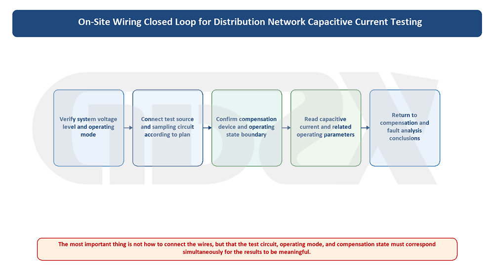
Figure: Closed-Loop Field Wiring for Distribution Network Capacitive Current Testing
How should the field wiring be connected? First confirm the operating conditions and PT requirements, then clarify the open-delta excitation and acquisition circuits, and finally perform the measurements in sequence with repeat verification.
In this section, we will walk the reader through the field testing process and explain the wiring and sequence for the PT secondary-side open-delta method, so that the entire procedure can be understood even without a diagram.
What components make up the measurement circuit? A typical open-delta off-frequency measurement circuit includes the secondary winding of the system potential transformer (PT), particularly the open-delta (residual-voltage) winding; the off-frequency signal injection/acquisition terminals of the tester; test leads connecting the secondary circuit to the tester; and the tester's internal signal source, acquisition, processing, and display units. The core principle is that the tester applies an off-frequency signal to the PT secondary-side open-delta circuit while simultaneously acquiring the circuit response, and then determines the system's equivalent capacitance to ground from the relationship between the excitation and response.
Why can a measurement performed on the low-voltage side reflect the capacitance to ground on the primary side? The key is that the PT maps the primary-system voltage to ground to the secondary side according to its transformation ratio. The imbalance of the system's three-phase capacitance to ground and the zero-sequence voltage appear as a residual-voltage response in the PT open-delta winding. Essentially, the open-delta winding reflects the zero-sequence component of the three-phase voltage, while the zero-sequence path is also the path through which capacitive current to ground flows. Therefore, by applying an off-frequency excitation to the open-delta circuit on the secondary side and measuring its response, the equivalent capacitance to ground of the primary-side system can be indirectly calculated through the PT ratio and equivalent circuit relationships, and the capacitive current can then be determined. Performing the work on the low-voltage side simply moves the “observation point” downward; the object being measured remains the capacitance to ground of the entire system.
Relationship among the open-delta winding, secondary-side signal, and system's equivalent capacitance to ground. This can be understood as follows: the system's capacitance to ground is the physical quantity being measured; through the electromagnetic coupling between the PT primary and secondary sides, it leaves observable electrical characteristics in the open-delta winding; the tester injects an off-frequency signal into the open-delta circuit and acquires the response, then uses the known injected quantity and PT parameters to “solve for” the unknown capacitance to ground. The three form a relationship of “measured quantity—mapping channel—observation and calculation.”
Prerequisites to confirm before testing. Before starting the field test, make sure to confirm: the current system operating condition (which lines are in service and whether loop transfer or closed-loop operation is involved); the PT configuration and ratio, and whether the open-delta winding is brought out and available for use; the system neutral grounding method (ungrounded, grounded through an arc-suppression coil, or grounded through a low resistance); the switching status of the arc-suppression coil (its compensation state can significantly affect the measurement and must be handled or its influence excluded as required by the equipment); the energized status of the lines and the applicable safety isolation measures; and whether the system parameters to be entered, such as rated voltage and PT ratio, are correct. Once any of these prerequisites is misunderstood or entered incorrectly, the subsequent measurement data may lose its validity.
Which wiring or field conditions are most likely to cause misjudgment? In practice, incorrect results are most likely under the following conditions: improper PT open-delta wiring or incorrect polarity/phase sequence, resulting in abnormal response signals; frequent switching of the system operating condition, causing the network configuration to change during measurement and making before-and-after data incomparable; strong harmonic interference at the site, which can contaminate the measurement if interference suppression is inadequate; the arc-suppression coil being in service while its influence is not correctly excluded, causing the measured value to represent the compensated quantity rather than the system's inherent capacitive current to ground; incorrect parameter entries, such as an incorrect PT ratio or rated voltage, causing an overall deviation in the calculated result; and abnormalities in the secondary circuit itself, such as poor contact, winding faults, or improper grounding, which can distort the acquired signal.
Recommended field testing sequence. The general procedure is: verify and record the system operating condition and grounding method → confirm that the PT open-delta winding is usable and inspect the secondary circuit → connect the test leads according to the equipment instructions and verify polarity and terminals → correctly enter system parameters such as voltage level and PT ratio → handle or clearly identify the switching status of the arc-suppression coil → start the off-frequency test and read the three-phase capacitive current to ground and equivalent capacitance to ground → repeat the measurement at least once to verify consistency → record, store, and export the results, and print them when necessary for traceability. The entire process emphasizes “confirm the prerequisites first, perform the measurement second, and verify the results afterward,” rather than simply connecting the instrument and reading the displayed value.


