


NEWSnews
Special Condition Simulation, Acceptance Criteria, and Fault Troubleshooting
七、Special Operating Condition Simulation Methods
7.1 Three-Phase Simultaneous Operation Simulation
Configure the three channels of the multi-channel device for simultaneous operation to ensure synchronized switching of the three-phase position contacts. The timing deviation shall remain within the limits specified by the applicable regulations (verify the specific tolerance against the current regulations).
7.2 Single-Phase Operation Simulation (Single-Phase Trip)
The three-phase channels operate independently and can respond separately to the trip and close commands for each phase without mutual interference.
Typical sequence: Apply an A-phase ground fault condition → the protection device issues an A-phase trip command → the A-phase channel switches to the open position → the B- and C-phase channels remain in the closed position → the protection device issues an A-phase reclosing command → the A-phase channel switches back to the closed position → if the fault persists, the protection device initiates an accelerated three-phase trip.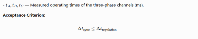
7.3 Three-Phase Discrepancy Protection Simulation
Manually set one phase to a position state different from the other phases, then verify whether the protection device operates within the specified time.
7.4 Circuit Breaker Failure (Failure-to-Trip) Simulation
Select the "Failure-to-Operate/Circuit Breaker Failure Mode" on the device. In this mode, the internal relay does not operate even when a voltage pulse is applied to the trip input, maintaining the current position state. If the protection device detects no change in position feedback after the circuit breaker failure protection initiation time has elapsed following the trip command, it triggers the circuit breaker failure protection logic.
Note: After completing the circuit breaker failure simulation, be sure to restore the device to normal operation mode and manually reset it to the correct initial position state before proceeding with the next test.
7.5 Reclosing Operation Simulation
The complete sequence of "trip—brief delay—reclose—retrip" must be verified. Requirements for the simulated circuit breaker: it must maintain the open position after tripping while waiting for the reclosing command; reliably switch to the closed position upon receiving the reclosing command; ensure stable switching time without contact chatter; and respond quickly upon receiving the subsequent trip command.
八、Acceptance Criteria and Operating Sequence Assessment
8.1 Components of Overall Protection Test Operating Time
Overall protection test recorded time = Protection operating time + Simulated circuit breaker operating time
Protection operating time = Overall protection test recorded time − Simulated circuit breaker operating time (measured calibration value)
When evaluating whether the protection operating time meets the acceptance criteria, the operating time of the simulated circuit breaker must be subtracted to obtain the actual operating time of the protection device itself.
8.2 Key Checks for Operating Sequence Assessment
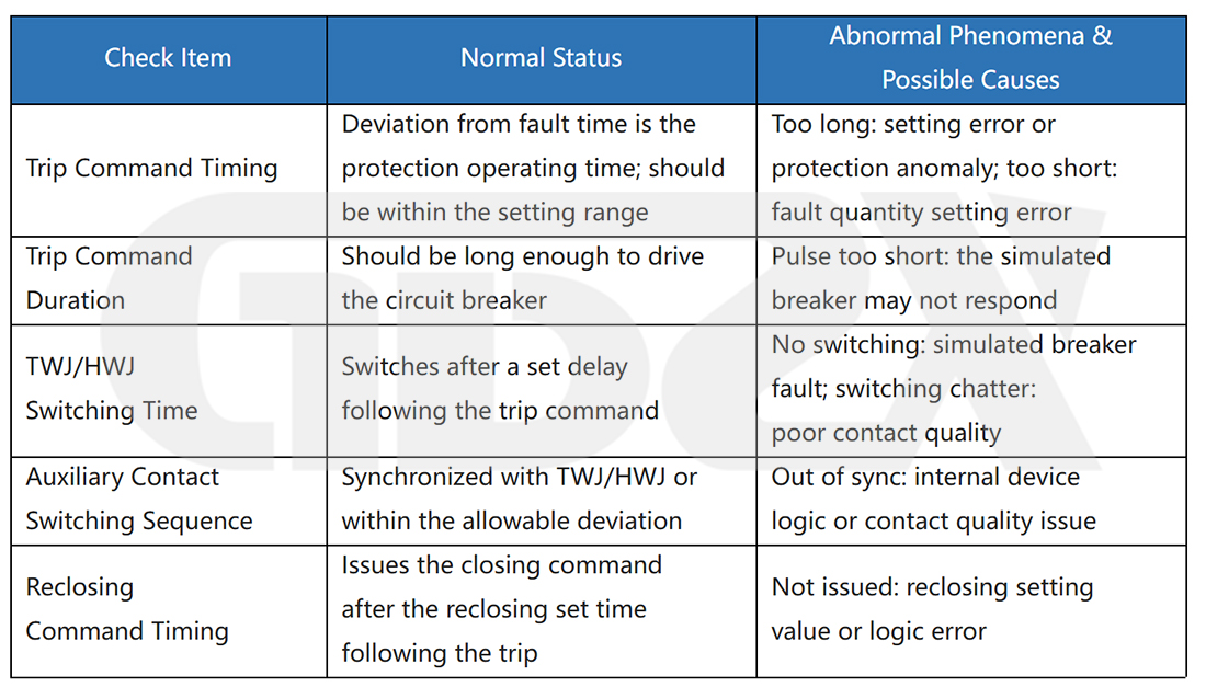
8.3 Acceptance Criteria for Overall Protection Tests (General Principles; Subject to Current Regulations)
1.The protection operating time, after deducting the simulated circuit breaker operating time, falls within the allowable tolerance of the set value.
2.The protection operates on the correct phase (single-phase faults trigger single-phase tripping; three-phase faults trigger three-phase tripping).
3.The switching states of the TWJ/HWJ/auxiliary contacts are correct, with no abnormal contact chatter or double-zero/double-one states.
4.The differences in operating times among the three phases fall within the tolerances specified by the applicable regulations.
5.The reclosing operation (if applicable) follows the correct timing and logic.
6.The circuit breaker failure protection (if tested) initiates and operates correctly within the specified time.
8.4 Common Calculation Formulas
Note: The following formulas are intended for engineering estimation purposes. Specific results should be evaluated in conjunction with the protection device manual and on-site measurement data. Any limits involved in the formulas should be verified against current regulations and the device technical specifications.
Formula 1: Protection Operating Time Correction Formula
During overall protection testing, the time recorded by the relay protection tester includes the operating delay of the simulated circuit breaker itself. This delay must be subtracted to obtain the actual operating time of the protection device.
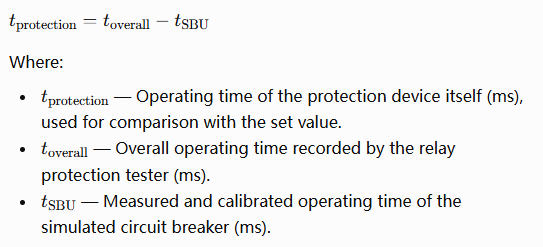
Important Note: \(t_{\text{SBU}}\) must be measured and calibrated using a high-precision time measurement instrument. The set value must not be used as a substitute for the measured value, as an inherent deviation exists between the two (the deviation may reach ±10 ms for basic models and can be controlled within ±1 ms for high-end models). Recalibration is required each time the setting level is changed.
Formula 2: Circuit Resistance Setting Matching Estimation
When selecting the resistance setting of a simulated circuit breaker, the objective is to make the simulated circuit resistance as close as possible to the actual resistance of the trip/close coil of the on-site circuit breaker.


Formula 3: Control Circuit Monitoring Voltage Calculation
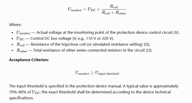
Engineering Note: When the resistance setting of the simulated circuit breaker is significantly higher than the actual coil resistance, \\(U\_{\text{monitor}}\\) may be substantially higher than its normal value, potentially causing the monitoring circuit current of the protection device to exceed the allowable range. Therefore, select a resistance setting as close as possible to the actual coil resistance.
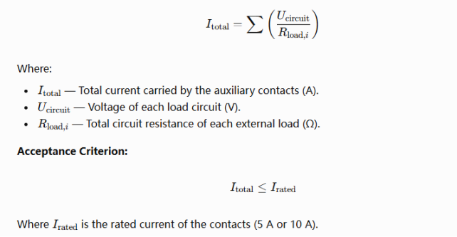
Formula 4: Auxiliary Contact Driving Capability Calculation
Example: For a DC 110 V circuit, the contacts simultaneously drive three protection digital inputs (approximately 5500 Ω each) and one remote signaling input of the monitoring and control system (approximately 2200 Ω):

This is well below the 5 A rated current and is safe.
If the contacts simultaneously drive five intermediate relay coils (approximately 110 Ω each):
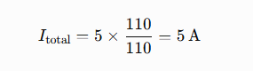
This reaches the rated current limit. A 10 A model or intermediate relays should be used instead.
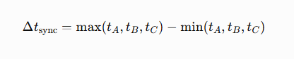
Formula 5: Three-Phase Operating Synchronization Assessment
Where:
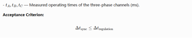
The specific tolerance shall be verified against current regulations and the manual of the protection device under test. The allowable deviation is typically on the order of several milliseconds.

九、Common Fault Symptoms and Troubleshooting Methods
9.1 Failure to Operate
Fault 1: Simulated Circuit Breaker Fails to Operate Upon Receiving Trip/Close Commands from the Protection Device
Troubleshooting: Use a multimeter to check whether DC voltage pulses are present at the trip/close input terminals → Verify that the voltage matches the device's rated input (DC 110 V or DC 220 V) → Confirm that the DC polarity is correct → Ensure that the device is not in "Circuit Breaker Failure/Failure-to-Operate Test Mode" → Check that the device power supply is functioning properly.
Fault 2: Intermittent Trip/Close Operation Failure
Key Checks: Oxidized or loose wiring terminals → Damaged connecting cables or poor contact → Insufficient trip/close command pulse width → Unstable DC power supply voltage.
Fault 3: Manual Operation via the Front Panel Works Normally, but the Device Does Not Respond When Linked to the Relay Protection Tester
Troubleshooting: Verify that the output contact circuit wiring of the relay protection tester is correct → Confirm that the driving power supply for the output contacts is correct → Check the linkage communication protocol configuration (ensure that the protocol type, baud rate, and address settings match).
9.2 Position Status Abnormalities
Fault 4: The Closing Circuit Operates Normally, but the Trip Circuit Has No Output (or Vice Versa)
Troubleshooting: Verify that the trip and close terminals have not been cross-wired → Use a multimeter to measure the input terminals of both circuits separately → Check whether either circuit has been disabled internally → Consider a fault in the internal trip or close branch circuit.
Fault 5: Open/Closed Position Indication Fails to Switch
Troubleshooting: Confirm that the trip/close command has been received → Check whether the relay is stuck (listen for the relay switching sound) → Power-cycle the device to attempt status initialization → Check the wiring of the TWJ/HWJ output terminals.
Fault 6: Frequent Remote Signaling Fluctuations and False Status Changes
Main Causes: Unstable contact due to relay contact wear; poor contact at wiring terminals; external interference; poor device grounding.
Corrective Actions: Install a parallel RC filter for contact debouncing (within permissible limits); check the device grounding; replace the device with a higher-quality model.
Fault 7: Unsynchronized or Incorrect Three-Phase Position Feedback
Troubleshooting: Check whether the operating time settings are consistent across all channels → Check for differences in wiring circuit impedance among channels → Investigate internal three-phase channel drive timing issues (contact the manufacturer). If the three-phase synchronization deviation exceeds the tolerance specified by the applicable regulations, the overall protection test result is invalid.
9.3 Timing Accuracy Issues
Fault 8: Large Deviation Between Set and Measured Trip/Close Operating Times
Causes: Low accuracy of the device timing control circuit; crystal oscillator aging; temperature effects.
Corrective Actions: Calibrate the actual operating time using a high-precision instrument, and use the calibrated value as a correction factor when processing overall protection test data.
Fault 9: Large Variations and Instability in Operating Time Across Repeated Tests
Causes: Loose wiring terminals; excessive DC power supply ripple; relay aging.
Corrective Actions: Tighten the wiring terminals; use a regulated DC power supply; replace the device with a model featuring high-precision electronic switching.
Fault 10: Three-Phase Operating Time Deviation Exceeds the Limit, Causing Overall Protection Test Failure
Corrective Actions: Calibrate the actual operating time of each channel individually and adjust the settings to make the measured operating times consistent. If the timing differences among the three-phase channels exceed the adjustable range, the device does not meet the required quality standards and should be replaced.
9.4 Control Circuit and Communication Faults
Fault 11: Persistent Control Circuit Disconnection Alarm Without Any Operation
Checks: Verify that the TWJ and HWJ wiring is connected correctly and separately → Confirm that the device is in a clearly defined open or closed position → Check whether the circuit resistance setting results in insufficient voltage at the protection device's digital input → Verify that the DC supply voltage is within the allowable range of the protection device.
Fault 12: No Response on One Phase While the Other Phases Operate Normally
Checks: Verify whether the trip/close input terminals for the affected phase are loose → Use a multimeter to confirm that the command voltage reaches that phase → Check for a possible fault in the internal optocoupler or relay of that phase channel → Verify that the power supply to the affected phase channel is functioning properly.
Fault 13: Communication or Linkage Failure with the Relay Protection Tester
Troubleshooting Sequence: Physical layer (wiring, RS485 polarity, and cables) → Link layer (baud rate, data bits, stop bits, and parity) → Application layer (protocol type, device address, and command format). First, switch to the hardware contact mode to verify device functionality, then troubleshoot the communication issues separately.
9.5 Hardware and Environmental Faults
Fault 14: Blank Screen, Garbled Display, Parameter Loss, or Unresponsive Keys
黑For a blank screen or garbled display, first try power-cycling the device to reset it. Parameter loss may indicate a memory fault or abnormal power supply and requires manufacturer support. Sticky or unresponsive keys can be addressed by cleaning.
Fault 15: Device Automatically Restarts or Powers Off After Multiple Remote Signaling Circuits Are Connected
This is a typical overload issue. Use external intermediate relays to increase the driving capacity, and calculate the total current of all external loads to ensure it does not exceed the device's rated contact capacity.
Fault 16: Device Overheating and Shutdown After Frequent Operations
Check whether the ventilation and heat dissipation are adequate; reduce the test frequency; check the ambient temperature. If overheating persists at normal operating frequency, it indicates insufficient thermal design of the device.


