


NEWSnews
Simulated Circuit Breaker: Structure, Standards & Protection Test Applications
四、Equipment Structure and Typical Wiring
4.1 Panel Structure
Typical configuration: Power switch and status indicator lights; open/closed position indicators (one set for each of phases A, B, and C); manual opening/closing buttons; operation time setting knob or DIP switches; terminal block (trip input, close input, TWJ output, HWJ output, auxiliary contact output, and power input); communication interface (high-end models).
4.2 Typical Wiring Configuration
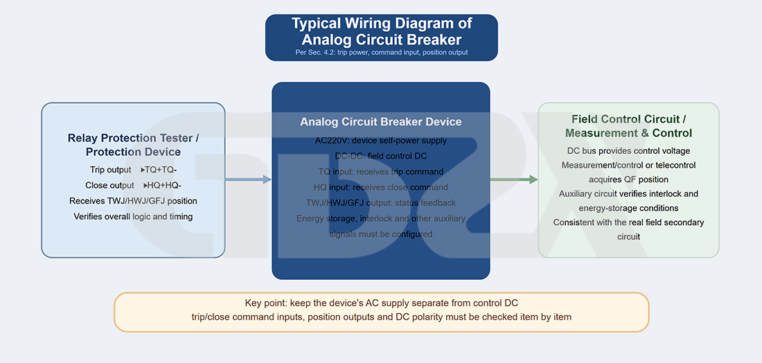
Figure 4-1 Typical Wiring Diagram of a Simulated Circuit Breaker
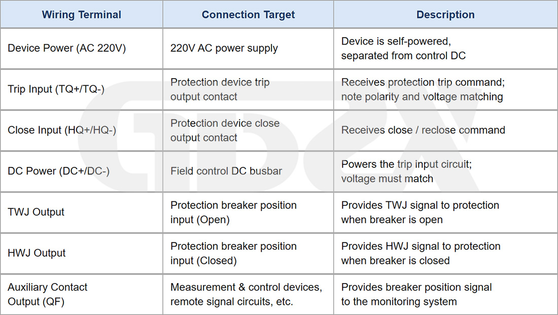
Safety Notice: Before wiring, ensure that the control DC voltage level matches the device's rated input voltage. Reversed DC polarity may damage the optocoupler or even the entire device. Use a multimeter to verify the voltage value and polarity before wiring. Apply power only after confirming that both are correct.
4.3 Typical Operating Procedure
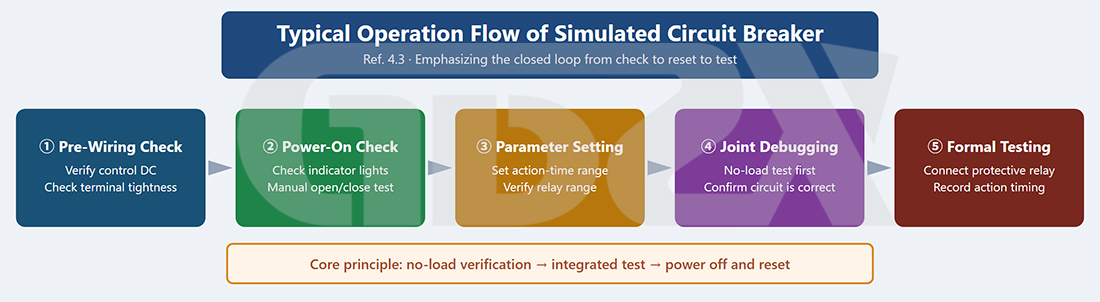
Figure 4-2 Typical Operating Procedure of a Simulated Circuit Breaker
1. Before Wiring: Verify the control DC voltage level and confirm that the specifications match the on-site requirements. Check that all terminal screws are securely tightened.
2. Power-On Inspection: Switch on the device and observe the indicator lights. Manually operate the open/close buttons to confirm that the TWJ/HWJ indicator lights switch correctly. Use a multimeter to verify the continuity of the auxiliary contacts.
3. Parameter Setting: Set the opening and closing operation times according to the test plan and confirm that the correct time settings are selected.
4. Integration Testing with the Relay Protection Tester: Perform an unloaded test first to confirm that the device responds correctly.
5. Complete Protection System Test: Connect the protection device and apply fault quantities in accordance with the test procedures. Record the operating times and sequence of events.
6. After Testing: Disconnect the DC power supply and the device power supply, remove the wiring, and organize the equipment.
五、Applicable Test Standards and Compliance Boundaries
5.1 Primary Applicable Standards
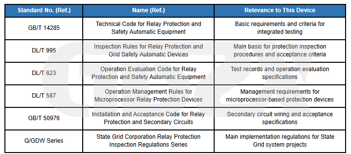
Important Notice: The standards listed above shall be subject to their currently valid versions. Before conducting formal tests, be sure to consult and verify the applicable standard versions. The standard numbers cited in this article must not be used as a substitute for reviewing the original standards.
5.2 Compliance Boundaries of the Simulated Circuit Breaker Itself
1.It is an axiliary tool, not an acceptance criterion in itself.
2.The operation time settings must comply with the requirements of the test procedures. Specific values shall be determined in accordance with the protection device manual and applicable test procedures.
3.The contact capacity and circuit parameters must be compatible with the protection device.
4.Test records should include the device model, operation time settings, measured operation times, and other relevant information.
六、Typical Applications in Complete Protection System Tests
6.1 Busbar Differential Protection System Test
The core logic of busbar differential protection is to identify the faulted bay and trip all associated circuit breakers. The complete protection system test must simulate the circuit breakers of multiple bays simultaneously to verify that the busbar differential protection operates correctly, isolates the faulted bay, and does not trip healthy bays incorrectly.
Usage: Configure an independent simulated circuit breaker channel for each bay involved in the test. Connect each channel in parallel to the corresponding bay's trip circuit of the busbar differential protection.
Key Considerations: The DC power supply polarity and grounding method of each bay's simulated circuit breaker must be consistent with the on-site circuit design. Synchronization between channels is critical when using multiple simulated circuit breakers. It is recommended to select a dedicated model that supports synchronized multi-channel operation rather than combining multiple single-channel units.
6.2 Automatic Transfer Switching (ATS) Protection System Test
The automatic transfer switching test must simulate the complete operating sequence: loss of the main power supply → tripping of the incoming circuit breaker → automatic closing of the standby circuit breaker. This involves sequential operation of at least two circuit breakers, with strict timing requirements: the incoming circuit breaker must trip before the standby circuit breaker closes. The timing coordination accuracy between the two channels of a dual-channel simulated circuit breaker directly affects the measurement accuracy of the automatic transfer switching operation time.
6.3 Line Protection System Test
A single-channel simulated circuit breaker is sufficient for most applications. When the auto-reclosing function is included, the simulated circuit breaker must reliably respond to the closing command issued by the protection device after an auto-reclosing command is generated and switch to the closed position, completing the full verification sequence of “tripping–reclosing–accelerated tripping.”
6.4 Circuit Breaker Failure Protection System Test
Circuit breaker failure protection testing is one of the scenarios in which a simulated circuit breaker demonstrates its greatest value. The key verification point is that after the protection device issues a trip command, the circuit breaker fails to open within the specified time (failure to operate), and the circuit breaker failure protection initiates the wider-range tripping logic once the preset detection time has elapsed.
The simulated circuit breaker must be able to simulate the condition in which it receives a trip command but does not operate (failure to trip), while continuing to maintain the closed position. This function cannot be implemented by an ordinary contact conversion board.
Key Configuration Requirements for Circuit Breaker Failure Protection Testing: Select a model that supports “failure/failure-to-trip mode.” In this mode, the device must remain inactive and maintain its existing closed position even when a voltage pulse is applied to the trip circuit. After the failure simulation ends, the device must be able to reset reliably.
6.5 Transformer Protection System Test
Transformer protection typically requires simultaneous control of the circuit breakers on all sides of the main transformer (high-voltage side, medium-voltage side, and low-voltage side). Therefore, a multi-channel model with three or more channels is essential for this application. Non-electrical protection functions (such as main tank gas protection and on-load tap changer gas protection) are typically simulated through independent contact inputs, so the simulated circuit breaker must provide sufficient binary input channels for coordination.


