


NEWSnews
Insulation Resistance Testing: Pitfalls, Selection & Vendor Review
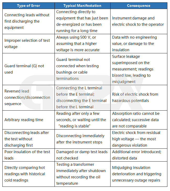
8. Common Operational Errors and Typical Misjudgments
9. How to Select an Insulation Resistance Tester: Define the Application First, Then Verify the Parameters
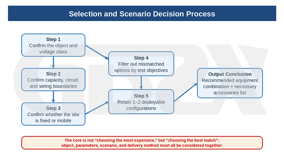
Figure: Selection Decision Process
Many articles stop at the point where “the principle has been explained and the test can be performed,” but when procurement and model selection are actually carried out, the questions of greatest concern are usually only two: first, which tier and which type of equipment should actually be purchased; second, which items in the manufacturer’s parameter table must be confirmed one by one, and which are merely marketing descriptions. Without this layer, selection guidance easily remains at the level of pure popular science.
To determine whether an insulation resistance tester suits your own needs, it is recommended to proceed in the order of “application first, parameters next, brand last,” rather than starting with a price comparison.
9.1 Clarify These Four Questions Before Selection
First, what equipment will be tested primarily? Secondary circuits, low-voltage motors, low-voltage cables, or 10 kV motors, 35 kV cables, and 110 kV main transformers? The type of equipment under test determines the test voltage ranges, the upper measuring limit, whether a G-terminal guard is required, and whether automatic calculation of the absorption ratio and polarization index must be supported.
Second, what is the highest voltage class that must be covered? If the highest voltage on site is only in the low-voltage system, the 500 V/1000 V ranges are often sufficient; to cover 6 kV–35 kV equipment, the 2500 V range is usually indispensable; if main equipment at 110 kV and above is involved, the 5000 V range is essentially a hard threshold. Clarifying this boundary first can directly rule out a large number of unsuitable models.
Third, will the results be reviewed informally, or formally archived with reports? For routine inspection, stable readings, automatic discharge, and complete safety functions matter more; if the tester is to be used for acceptance tests, preventive tests, third-party services, or audit traceability, then data storage, communication export, time stamps, report software, and calibration certificates are not optional extras but necessities.
Fourth, in what environment will it be used primarily? Indoor switchrooms, outdoor substations, damp station buildings, and extended field work impose entirely different requirements on power supply, ingress protection, anti-interference capability, and portability. An instrument that performs well in the laboratory may not work well at an outdoor site in summer.
9.2 Key Parameters to Verify During Procurement
The following parameters are the items that should truly be confirmed one by one during selection:
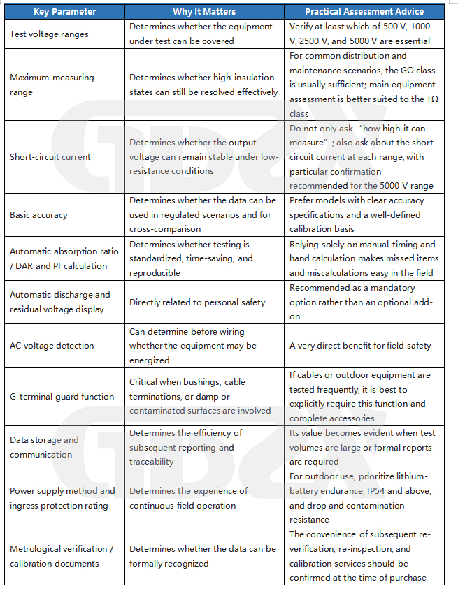
If this chapter is to truly guide procurement rather than remain at the conceptual level, then at least the following suggestedparameter linesshould be stated clearly. They are not mandatory provisions that replace standards, but very practical engineering minimums for selection, making it easy to screen models quickly when reviewing parameter tables.
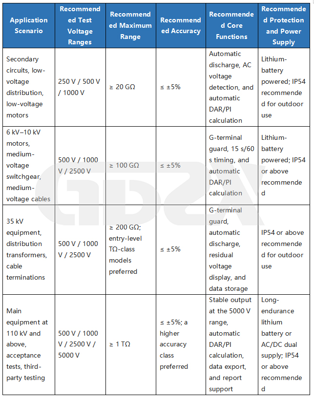
Furthermore, what truly influences the procurement decision is not merely “having this function,” butwhether the function is backed by supporting parameters. It is recommended to continue verifying the following items one by one:
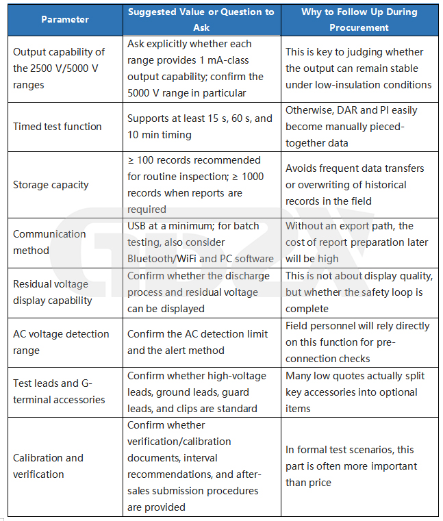
For tendering, price comparison, or internal project approval, the following wording is more useful than empty phrases such as “full-featured and stable in performance”:
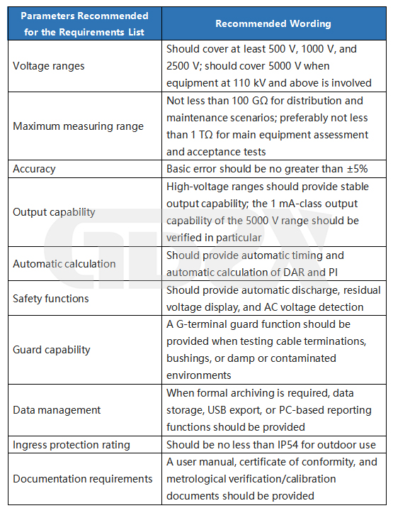
9.3 Three Points That Are Easily Overlooked but Are Actually the Most Critical
First, do not look only at the “maximum test voltage”; check whether it truly covers your equipment spectrum. For example, an instrument with a 5000 V range is not necessarily suitable for every scenario. If you routinely test low-voltage circuits as well as 10 kV motors and also need to cover 35 kV cables, then having the complete set of 500 V, 1000 V, 2500 V, and 5000 V ranges matters more than simply “how high the maximum voltage is.”
Second, do not ignore the short-circuit current. This is the parameter most easily glossed over in many procurement tables, yet it directly affects the credibility of measurements under low-insulation conditions. When the short-circuit current is insufficient, the output voltage will sag once the instrument encounters damp, contaminated, or locally degraded objects, and the resulting readings may appear valid but are not necessarily trustworthy.
Third, do not treat automatic discharge, residual voltage display, and AC voltage detection as “nice-to-have extras.” At real high-voltage sites, these functions are closer to “baseline safety configuration.” As long as the article addresses actual procurement rather than laboratory demonstration, these items should be placed on the mandatory requirements list.
9.4 A Simple and Practical Selection Approach
If the primary application islow-voltage distribution, secondary circuits, and general motor maintenance, it is recommended to focus directly on this set of parameters:250 V/500 V/1000 V ranges complete, with a maximum range of no less than 20 GΩ, basic error no greater than ±5%, with automatic discharge, AC voltage detection, and automatic DAR/PI calculation. This configuration already covers the vast majority of low-voltage maintenance scenarios.
If the primary application is6 kV–35 kV cables, motors, switchgear, and distribution transformers, it is recommended to raise the parameter threshold to: at least 500 V/1000 V/2500 V, with a maximum range of no less than 100 GΩ, and ideally reaching 200 GΩ or above, together with G-terminal guard,15 s/60 s/10 min timing,automatic DAR/PI calculation and automatic discharge. If an instrument in this class only claims that “it can reach 2500 V” but its range, timing, and guard capability are unclear, it is generally unsuitable for serious field use.
If the primary application isacceptance tests at 110 kV and above, preventive tests on main equipment, and third-party testing, it is recommended to state the requirements more explicitly: should cover 500 V/1000 V/2500 V/5000 V full ranges, with a maximum range of no less than 1 TΩ; at the 5000 V range, particular attention should be paid to the 1 mA-class output capability, along with data storage,USB export or PC-based reporting,automatic DAR/PI calculation,residual voltage display, andmetrological calibration documents. For such scenarios, the ability to form a closed-loop data trail matters far more than simply “how big the screen is or how many menu items there are.”
If it is used mainly fortraining, teaching, and emergency backup, the range and data management requirements may be relaxed appropriately, but digital instruments are still recommended. A practical configuration is 500 V/1000 V/2500 V ranges, automatic discharge, and basic timing functions; traditional hand-cranked testers are better suited as supplements for teaching demonstrations and are not recommended as the primary test equipment.
10. How to Tell Whether an Insulation Resistance Tester Manufacturer Is Reliable
The real dividing line often lies not in “whether it can measure,” but in “whether the measurement is compliant, reproducible, and easy to implement in the field.” The reliability of a manufacturer should be assessed against the following five points. First, metrological qualification: whether type evaluation certificates or factory conformity certificates issued by statutory metrological bodies can be provided, and whether periodic submission for verification is supported. Second, standard conformity: whether the product manual explicitly states compliance with IEC 61557 or the corresponding national standards. Third, after-sales service: the response speed and network coverage of metrological calibration and repair services. Fourth, field reputation: actual application cases in similar projects (power transmission and transformation acceptance, preventive testing). Fifth, parameter transparency: whether the short-circuit current and upper range limits are stated with the corresponding test conditions rather than vaguely labeled.


