


NEWSnews
Insulation Resistance Test: Equipment, Core Queries & Test Specifications
5. Applicable Equipment Scope
Insulation resistance testing has a very wide range of applications, and transformers are only its most typical scenario:
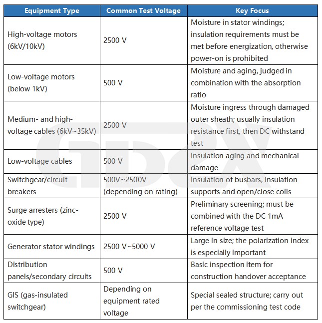
6. Systematic Review of Six Categories of Core Questions in Practice
The following are the core questions repeatedly raised in training, field O&M and equipment procurement consulting, systematically analyzed in six groups by the nature of each question. Although these questions appear independent, they often point to the same root cause: a lack of systematic understanding of the method boundaries, operating logic and evaluation criteria of insulation resistance testing.
6.1 Standards: How to Select Test Voltage and Determine Acceptance Values
A higher test voltage is not necessarily better; it must match the insulation strength of the equipment under test. Equipment of different voltage classes differs greatly in insulation thickness and insulation strength. The applied test voltage must be sufficient to excite potential defects while not exceeding the withstand capability of the insulation. Below is the industry-standard reference correspondence (in actual practice, consult the applicable current standard clauses):
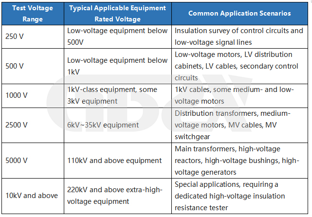
Behind the dividing line between 2500V and 5000V lies the essential difference in insulation structure between 35kV and 110kV equipment. For distribution equipment at 35kV and below, the 2500V range already meets standard requirements; whereas for main transformers at 110kV and above, testing at only 2500V provides insufficient diagnostic resolution of the insulation condition and is not accepted in formal commissioning test reports — the 5000V range is mandatory.
The root cause of "different people giving inconsistent statements" in the field is that different versions of standards, different equipment types and different test natures (commissioning vs. preventive) inherently differ in their provisions on test voltage, with no unified fixed correspondence. This is exactly why every test must consult the current valid standard applicable to the equipment under test, rather than relying on rule-of-thumb assumptions.
Regarding acceptance values, there is likewise no universal fixed figure. There are three fundamental reasons: First, insulation thickness varies greatly among voltage classes of the same equipment type — the normal insulation resistance of a 6kV transformer and a 110kV transformer are not in the same order of magnitude at all. Second, insulation resistance is strongly affected by temperature; the resistance roughly doubles for every 10°C change, so without temperature conversion the values are not comparable. Third, standards themselves are updated over versions — DL/T 596-2021 has already adjusted some clauses relative to earlier versions, and different sites cite different versions, so statements naturally vary. The proper evaluation path is: consult the applicable current standard, take readings at multiple time points at the correct temperature, calculate the absorption ratio and polarization index, compare longitudinally with historical records, and make a comprehensive assessment. This is also why many codes emphasize "no lower than a certain proportion of the previous test result" — the historical trend reflects the true evolution of the insulation better than any single absolute value.
6.2 Principles: Deeper Understanding of the Measurement Mechanism and Wiring Logic
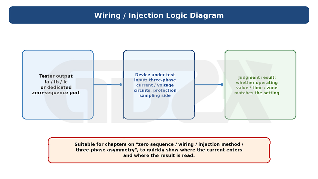
Figure: Wiring logic diagram
Insulation resistance testing is by no means about reading a single value. As described in Chapter 1, the current flowing through the insulation after a DC high voltage is applied is the superposition of three components that dynamically decay over time. "When to read" is part of the standard — the 15s value reflects the initial state before the charging current has decayed, the 60s (1-minute) value is the most frequently cited primary value, and the 1min and 10min values are used to calculate the polarization index. The three together form a complete evaluation system; any one taken alone is one-sided.
After the low-voltage side is short-circuited and grounded, why can insulation resistance still be measured? This is where beginners are most easily confused when understanding transformer wiring logic. Many think: if the LV side is grounded, doesn't that connect the HV and LV sides? In fact, no. What is measured is the resistance of the insulation layer between the "HV winding conductors" and the "LV winding conductors + core/tank", not the conductors themselves. The test current enters the HV winding from the instrument's L terminal and, to return to the E terminal (ground), must pass through the insulation layer between HV and LV — it is precisely the resistance of this insulation layer that is the measurement object. Grounding the LV side provides a return path for the leakage current and fixes the LV side at the reference zero potential, preventing induced voltages from disturbing the measurement. If the LV side were left floating, the induced potential would superimpose on the measuring circuit, distorting the data and endangering the operator.
The role and timing of use of the guard terminal (G terminal)This is another frequent question at the principle level. The instrument's G terminal is by no means an optional accessory — when there is surface leakage current on the insulation under test (e.g., contaminated bushing surfaces, high test-environment humidity, moisture in HV cable termination insulation), this surface leakage current, if left untreated, will superimpose into the instrument's measuring circuit, causing a falsely low insulation resistance reading and misjudgment. The G terminal works by diverting the surface leakage current into the guard circuit so that it does not flow through the measuring circuit, thereby measuring the true volume insulation resistance. Whenever testing involves bushings, HV cable terminations, or outdoor equipment in high-humidity environments, the guard terminal should be connected — a step that is skipped surprisingly often in the field.
6.3 Operations: Wiring Methods and Operational Details
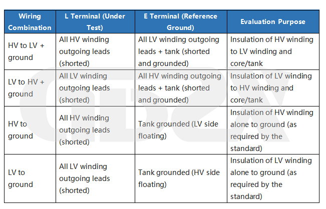
Why must all outgoing leads of the side under test be short-circuited in transformer insulation resistance testing, instead of connecting just one lead? The reasons are twofold: First, although the three-phase windings are internally connected, there may be broken wires, poor contact, or a floating tap changer between the external terminal and the internal winding connection points; without external short-circuiting, there is no way to ensure every phase is included in the measuring circuit. Second, external short-circuiting puts all conductors under test at equal potential, eliminating the possibility of dangerous induced potentials on unconnected terminals. This is not an optional action but a prerequisite for accurate results and safe operation. The four typical wiring combinations are as follows:
When an oil-immersed transformer has just been taken out of service, the effect of temperature on the test result must not be overlooked. Right after shutdown, the oil temperature of a transformer is often high, and the insulation resistance measured at that time will be significantly lower than the value measured in the cold state (near ambient temperature). Comparing hot-state values directly with historical cold-state data can easily lead to a false judgment of insulation degradation. The proper practice is to wait until the equipment has cooled to near ambient temperature before testing, or to record the top-oil temperature and perform temperature conversion; moreover, the oil temperature and ambient temperature must be faithfully recorded at every test to provide a convertible baseline for comparison across tests.
The order of disconnection matters, and it is not formalism. The correct orderis: stop the instrument output, confirm that discharge is complete, remove the L-terminal test lead first, and remove the E-terminal ground lead last. The reason the order cannot be reversed: before the L terminal is removed, the E-terminal ground connection is the last safeguard ensuring that any residual charge on the equipment under test is safely drained. If the E terminal is removed first, the equipment's grounding loop is broken; if any residual charge remains, a floating high potential will form on the equipment, exposing the operator to electric shock when touching the L-terminal lead.
6.4 Safety: Voltage Verification, Discharge and Protection Requirements
Why verify voltage and discharge when the power is already off? These two operations may seem redundant, but in fact they are two independent life-safety barriers.
Completing the de-energization operation does not guarantee that the equipment is truly de-energized. Power systems carry risks such as improperly executed switching orders, incorrectly operated disconnectors, and back-feed from adjacent equipment. The purpose of voltage verification is to prove by physical means — phase-by-phase confirmation with a qualified voltage detector — that the equipment is genuinely de-energized, rather than inferring it from the switching order alone. Omitting voltage verification in any form is a serious violation.
Discharge addresses another source of danger: even after the HV supply side is confirmed de-energized, the insulation of the equipment under test may still hold a large amount of static charge accumulated during long-term operation, especially in equipment with large capacitance such as large transformers, long HV cable runs and capacitor banks. Connecting test leads without adequate discharge exposes personnel to stored energy sufficient to cause injury or death, regardless of whether the equipment is energized.
How long should the discharge last? This is the step most easily shortened or even skipped in the field. Measured data show that after a large transformer is tested at 5000V for 10 minutes, several hundred volts can still remain on the equipment when the instrument output is cut off. It is generally recommended that the discharge time be no shorter than the test time and at least 1~2 minutes, longer for large-capacity equipment; after discharge, a voltage detector should be used to confirm that the residual voltage has dropped to a safe level. The main reasons this step is neglected are that residual high voltage is imperceptible to the eye and schedule pressure leads operators to treat it as "meaningless waiting" and skip it — one of the most dangerous violations in insulation resistance testing.
Both the operator and the supervisor must wear insulating protective equipment, for two reasons. The operator works directly in a DC high-voltage environment; insulating gloves, insulating shoes and insulating mats are the basic barriers against electric shock. The supervisor is in the same danger zone as the operator, faces the same risk of accidental shock, and needs the same protection. More importantly, the supervisor's duty is to take immediate action if the operator has an emergency; if the supervisor is not properly protected, the rescue itself becomes a new source of injury. The two-person system of "one operating, one supervising" is the basic safety guarantee against being unable to self-rescue in an emergency when working alone, and must not be simplified.
6.5 Instrument Selection: Differences Between Instruments and Procurement Points
The differences among analog megohmmeters, digital insulation resistance testers and smart instruments go far beyond appearance. The core differences lie in output voltage stability and data management capability.
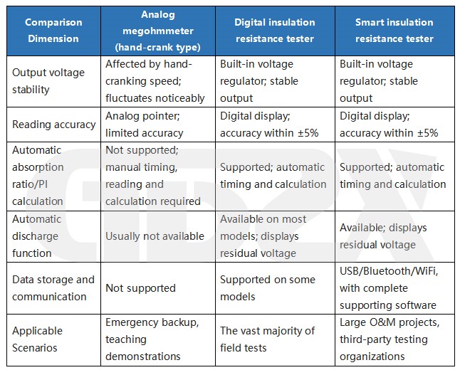
The biggest technical limitation of the traditional hand-crank megohmmeter is that steady cranking (about 120 r/min) is the prerequisite for stable output voltage, and uneven cranking speed causes reading fluctuations. Digital instruments regulate voltage internally, fundamentally eliminating this problem, and are the mainstream choice for modern formal testing. The additional value of smart instruments lies mainly in data management efficiency, making them suitable for scenarios with heavy test workloads and formal reporting requirements. If your current top concern is "which type of instrument to buy and how to verify the specifications", go straight to the selection checklist in Chapter 9.
The parameters that truly matter in procurement are not the longest list on a quotation, but the following core indicators:
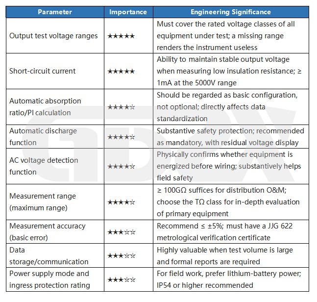
Short-circuit current is the most easily overlooked yet genuinely important parameter. When the insulation resistance of the equipment under test is extremely low (moisture ingress or partial breakdown), the instrument needs sufficient short-circuit current to maintain a stable output voltage. If the short-circuit current is too small, the output voltage sags during the test and the measured values are distorted — be sure to inquire range by range when purchasing.
6.6 Misconceptions: Which Judgments Are Wrong
A good insulation resistance does not necessarily mean the insulation is problem-free. This is the most common and most insidious judgment error in engineering practice. Insulation resistance testing reflects macroscopic overall DC resistance characteristics, and its detection boundary is clear: for localized defects (tiny voids inside insulation, localized carbonization points, slight localized moisture), early microscopic degradation, and latent breakdown hazards that are excited only under high electric field, insulation resistance testing has almost no resolving power. A piece of equipment with perfectly normal insulation resistance may break down in a withstand voltage test; its dielectric loss value may already be noticeably elevated, indicating microscopic degradation inside the insulation; a partial discharge test may also reveal discharge defects. Conversely, a low insulation resistance must not simply be equated with "the equipment is bound to fail" — measurements in high-temperature, high-humidity environments will be significantly lower, and drawing hasty conclusions without temperature conversion and historical comparison is equally a misjudgment.
Insulation resistance testing, withstand voltage testing, leakage current testing and dielectric loss testing differ in purpose and emphasis and cannot substitute for one another. The withstand voltage test "examines" the insulation at or above rated voltage and can reveal weak points and imminent breakdown risk, but it is somewhat destructive and may only be performed after the insulation resistance test has passed — this is the standard test-sequence logic. The leakage current test is methodologically close to insulation resistance testing, both applying DC high voltage, but it precisely records the leakage current curves at each voltage level, with markedly higher sensitivity to early insulation degradation, making it suitable as an enhanced evaluation means for important equipment. The dielectric loss test evaluates the degree of microscopic degradation inside the insulation, with sensitivity to moisture and early aging far exceeding that of insulation resistance testing; it is not uncommon for a large transformer to show normal insulation resistance but elevated dielectric loss. Each has its own role and should be reasonably combined according to equipment importance and test purpose, rather than assuming that an insulation resistance test makes the other methods dispensable.
7. Full Testing Workflow: Standardized Operations Before, During and After Testing
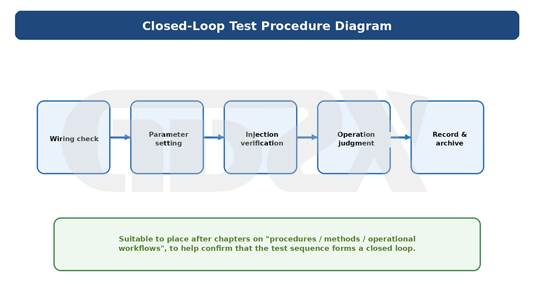
Figure: Testing workflow diagram
Preparation Before Testing
Step 1: Confirm that the equipment is de-energized and isolated, and that voltage verification and grounding have been completed. This is a safety prerequisite that must not be skipped; any operation performed before it is a violation.
Step 2: Fully discharge the equipment under test. Static charge may still be stored in the insulation of de-energized equipment; discharge time is usually no less than 1~2 minutes, and longer for large-capacity equipment.
Step 3: Record the ambient temperature and humidity (for transformers, the top-oil temperature must be recorded). This is the foundation for comparability of data across tests.
Step 4: Clean the insulation surfaces under test (bushings, leads, etc.) to reduce the interference of surface leakage on the measurement.
Step 5: Check the instrument's condition: sufficient battery, intact test-lead insulation, and normal functions.
Standardized Operations During Testing
First connect the E terminal (ground lead) to the grounding point, then the L terminal to the conductor under test, and the G terminal (guard) as needed. After confirming the wiring is correct, start the instrument's high-voltage output. Strictly take and record readings at 15s and 60s; for large equipment, additionally read the 1min and 10min values and calculate the absorption ratio and polarization index. During the test, no personnel may touch the equipment under test. Operators must wear insulating gloves and insulating shoes; supervisors must have the same protection and be present throughout.
Discharge and Lead Removal After Testing
After the test, stop the instrument output and wait for automatic discharge to complete (or discharge manually by grounding), then use a voltage detector to confirm that the residual voltage has dropped to a safe level. Remove the L-terminal test lead first and the E-terminal ground lead last; the order must not be reversed. After completion, close out according to the work permit.


