NEWSnews
Operation Method Of Phase Voltammeter
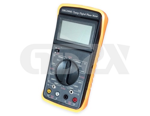
Phase voltammeter can measure current, voltage, phase, phase difference, but also can distinguish phase sequence and load. Next, GDZX explains how to operate it.
I Measuring voltage
Turn the functional range switch to the 500V limit corresponding to parameter U1, and input the voltage of the equipment under test from the U1 Jack to start the measurement. If the measured value is less than 200V, the 500V limit can be adjusted to 200V limit measurement directly by rotating the switch, so as to improve the measurement accuracy.
The two channels have the same voltage test characteristics. Therefore, the switch is rotated to the test limit corresponding to parameter U2, and the voltage of the equipment under test is measured from the input of U2 Jack.
II Measuring current
The operation of measuring current is similar to that of voltage measurement. Adjust the rotary switch to the 10A limit corresponding to parameter I1, insert the outlet plug of secondary side of clamp current transformer with label of I1 into I1 jack, and clamp the jaw on the measured line to conduct measurement. Similarly, if the measurement value is less than 2a, the switch can be directly rotated to the 2A limit measurement corresponding to I1 to improve the measurement accuracy.
When measuring the current, the rotary switch can also be turned to the limit corresponding to the parameter I2, and the measuring clamp labeled I2 is connected to the I2 jack, and the jaw of the clamp is clamped on the measured circuit for measurement.
III Measuring phase
When measuring the phase angle of U2 lagging U1, turn the switch to parameter U1U2. During the measurement process, the switch can be turned clockwise to each limit of parameter U1 to measure the input voltage of U1, or the switch can be turned anticlockwise to each limit of parameter U2 to measure the input voltage of U2.
Note: during phase measurement, the symbols U1 and U2 beside the voltage input jack and the red "*" symbol of the clamp current transformer are the terminals with the same phase name.
IV Measurement difference
When measuring the phase angle of I2 lagging I1, turn the switch to parameter I1I2. Similarly, during the measurement process, the input current of I1 can be measured by turning the switch clockwise to each limit of parameter I1, or the input current of I2 can be measured by turning the switch anticlockwise to each limit of parameter I2.
Input the voltage from U1, input the current from I2 with I2 measuring clamp, rotate the switch to parameter U1I2, and measure the angle of current hysteresis voltage. During the test, the switch can be turned clockwise to measure current at each limit of parameter I2, or anticlockwise to measure voltage of parameter U1.
The voltage can also be input from U2, the current is input from I1 with I1 measuring clamp, and the switch is rotated to parameter I1U2 position to measure the angle of voltage hysteresis current. In the same way, the switch can be rotated at any time to measure the value of I1 or U2.
V Distinguishing phase sequence
1. Three phase three wire distribution system
Turn the switch to U1U2 position. Connect phase a of three-phase three wire system to U1 jack, B-phase to ± jack corresponding to U1 and ± jack corresponding to U2, and C-phase to U2 Jack. If the measured phase value is about 300° at this time, the measured system is in positive phase sequence; if the measured phase is about 60°, the measured system is in negative phase sequence.
To change a measurement method, connect phase a to U1 jack, B phase to ± Jack and U2 socket corresponding to U1, and C phase to ± jack corresponding to U2. At this time, if the measured phase value is 120°, it is positive phase sequence; if the measured phase value is 240°, it is negative phase sequence.
2. Three phase four wire system
Turn the switch to U1U2 position. Connect a phase to U1 jack, B phase to U2 jack, and connect zero line to ± jack of two input circuits at the same time. If the phase is about 120° it is positive phase sequence; if it is 240° or so, it is negative phase sequence.
VI Load discrimination
Turn the switch button to U1I2 position. The load voltage is connected to U1 input terminal, and the load current is connected to I2 jack through measuring clamp. If the phase is in the range of 0° to 90° the measured load is judged as inductive; if the phase is in the range of 270° to 360° the measured load is judged as capacitive.
GDZX is a power testing equipment manufacturer, specializing in the production of phase volt ampere meter, more volt ampere phase meter model please see the details.


