


NEWSnews
Procurement Specs, Test Configs, Scenarios & Budget of Multi-phase Relay Testers
4. Six Core Parameters to Check Before Procurement
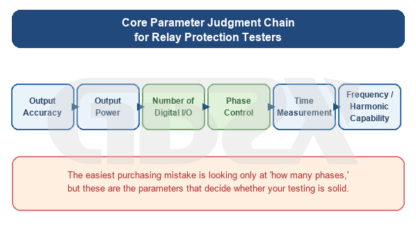
Figure: Core Parameter Decision Chain of Relay Protection Tester
When comparing products, many procurement staff are confronted with dozens of specifications on manufacturers’ parameter sheets and do not know which are critical and which are merely filler. In light of common issues in current procurement and delivery, the following six parameters are the most worth spending time comparing.
First, take a look at an overview table to get an intuitive sense of the differences in core parameters across equipment tiers:
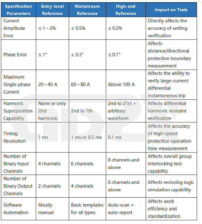
The following breaks down each key parameter in turn.
4.1 Output Accuracy (Voltage Accuracy, Current Accuracy, Phase Accuracy)
Why it matters: The core of relay protection testing is "accurately simulating faults." If the current value output by the tester itself has a 0.5% deviation, is the protection operation value you measure an error of the protection device or an error of the tester?
Here is a practical example: a certain overcurrent Zone II setting current is 5.0 A (secondary value), and the device technical specification requires an operation error not exceeding ±3%. If the tester's own current output accuracy is only ±1%, then at a 5.0 A output there is already an instrument error of ±0.05 A; even if the protection device is completely correct, the operation value you measure may fluctuate between 4.95 A and 5.05 A. A device with poorer accuracy yields less trustworthy test data. When verifying protections with higher sensitivity requirements (e.g., zero-sequence protection, or near the restraint knee point of differential protection), accuracy differences may directly affect the test conclusion.
Procurement baseline: Current accuracy ≤0.2% (of reading), voltage accuracy ≤0.2% (of reading), phase accuracy ≤0.5°. This is the level of current mainstream mid-to-high-end equipment. Low-end equipment may be rated at 0.5% or even 1%, which may suffice for simple overcurrent protection setting verification but falls short when faced with the impedance-loop accuracy requirements of distance protection.
Procurement reminder: Be careful to distinguish between "full-scale accuracy" and "reading accuracy." Some manufacturers state full-scale accuracy (e.g., full scale 30 A, accuracy 0.2%, meaning the error is ±0.06 A at any output value), while others state reading accuracy (error ±0.02 A at 10 A output, ±0.002 A at 1 A output).Reading accuracy has a clear advantage at small-signal output, and relay protection tests often require sensitivity verification in the small-current range, so the reading-accuracy rating is more favorable to the purchaser. When you get the parameter sheet, first confirm the accuracy reference basis.
4.2 Output Power (Current Output Capacity)
Why it matters: The current circuit of a relay protection device has impedance (including the input impedance of the protection device itself and the impedance of the connecting wires). For the tester to "push" the target current value in this circuit, sufficient output power (voltage × current) is required. If the power is insufficient, the current cannot be pushed up and the test cannot be performed.
In addition, verifying differential instantaneous trip protection usually requires injecting a large current more than 5 times the rated current (above 25 A under the 5 A CT system); if the tester's maximum single-phase current is only 20 A, this test cannot be completed.
Procurement baseline: A single-phase current channel power ≥40 VA is the basic threshold. The maximum single-phase current is recommended to be no less than 80 A (5 A CT system). For on-site tests requiring long wire connections, or for verifying old electromagnetic protection devices (with larger input impedance), a single-phase channel power ≥80 VA is recommended.
Procurement reminder: Note the difference between "single-phase power" and "three-phase combined power." Some manufacturers state the maximum current output capability after three-phase paralleling, e.g., "maximum 120 A" — which is actually the total current value of the three-phase current channels connected in parallel; the single-phase maximum is only 40 A. Three-phase parallel output scenarios are rare in actual testing and cannot be used as a reference for daily-use power.
4.3 Number of Binary Inputs and Outputs
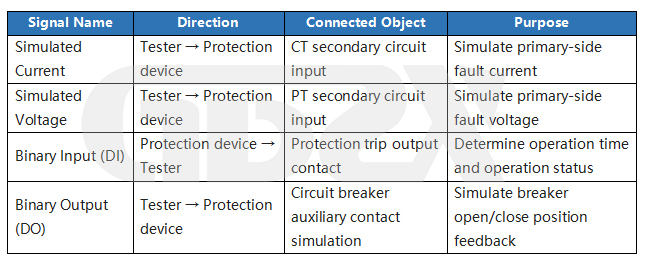
Why it matters: "Binary input" is the channel by which the tester receives contact signals such as trip/close/alarm output from the protection device; "binary output" is the channel by which the tester sends signals such as simulated breaker open position (TWJ)/closed position (HWJ) to the protection device.
The signal flow is as follows:
Example of practical impact: A typical line protection device has output signals including: trip phase A, trip phase B, trip phase C, three-phase trip, reclosing output, and alarm signal. If your tester has only 2 binary inputs, you can connect only 2 signals at a time and must rewire for the rest — low efficiency and repeated wiring raises the risk of misconnection. With 8 binary inputs, all these signals can be connected at once and captured in a single test run.
What deserves special attention is:Insufficient binary outputs means the reclosing test cannot be performed. The reclosing test requires the tester to simulate the breaker open/close position feedback (HWJ/TWJ) through binary outputs; if the number of outputs is insufficient, the complete group interlocking sequence cannot be fully executed.
Procurement baseline: Basic equipment: binary inputs ≥4, binary outputs ≥2. Mid-to-high-end equipment: binary inputs ≥8, binary outputs ≥4. For six-phase equipment used in differential protection or bus protection joint debugging, binary inputs ≥8 and binary outputs ≥4 are recommended.
Procurement reminder: The capacity of the binary output signals (the voltage and current they can withstand) also deserves attention. Some low-end devices' binary output contacts can only withstand 48 V/0.5 A, while some protection devices' binary input circuits require 110 V DC to be effectively recognized — when the output capacity is insufficient, an external intermediate relay is needed for conversion, making on-site wiring more complicated.
4.4 Phase Control Accuracy and Range
Why it matters: The concept of "direction" in relay protection relies entirely on the phase relationship between voltage and current to determine. Distance protection requires calculating the impedance value from the phase relationship between voltage and current.
Taking distance protection as an example, the method by which the tester simulates fault impedance is:
Z_sim = U_output ÷ I_output
Impedance angle φ_Z = arctan(X_sim ÷ R_sim)
The typical impedance angle of a transmission line is 70°~80°. If the tester's phase control accuracy is insufficient, e.g., with an inherent deviation of 0.5°, the "forward 75° impedance angle" you set may actually be 74.5° or 75.5° — in an impedance boundary test, this deviation may cause the protection device's direction judgment to err, making the test results unreliable and non-repeatable.
Procurement baseline: The phase control range is continuously adjustable from 0° to 360°, with accuracy ≤0.5° (some high-end equipment can reach 0.1°). For scenarios requiring precise distance protection verification, the higher the phase accuracy, the better.
4.5 Time Measurement Accuracy
Why it matters: The "selectivity" of relay protection is achieved through time grading — the operation time difference between upper- and lower-level protections is usually only a few hundred milliseconds or even tens of milliseconds.
What must be specially understood is: "setting the instantaneous trip protection to 0 s" does not mean a physical zero time delay. The inherent operation time of a microprocessor-based protection = sampling window time (about 20~40 ms) + hardware response time, totaling about 20~50 ms. Setting "instantaneous" only means the protection logic adds no extra delay; only above 100 ms does troubleshooting become necessary. This background knowledge will help you correctly judge the measurement results during acceptance —do not suspect a device fault just because the instantaneous trip measures tens of milliseconds。
Procurement baseline: Time measurement resolution ≤1 ms, accuracy ≤1 ms + 0.1% of reading. High-end models can reach 0.1 ms resolution.
4.6 Frequency Output Range and Harmonic Superposition Capability
Why it matters: Under-frequency load shedding protection and frequency relay verification both require the tester to output AC signals with adjustable frequency. In addition, the differential protection'sharmonic restraintverification is an easily overlooked but very important function.
When a transformer is energized unloaded, inrush current is generated, which contains rich second-harmonic components (100 Hz). Differential protection uses harmonic restraint to prevent maloperation during inrush:
Criterion: I_2nd ÷ I_1st ≥ K_2H → judged as inrush → block differential protection
K_2H is the harmonic restraint ratio setting (typical setting about 15%~20%, subject to the device setting)
If your tester does not support harmonic superposition output, this test cannot be completed.
Procurement baseline: The frequency output range covers 20 Hz~200 Hz, with frequency accuracy ≤0.01 Hz. Harmonic superposition capability: equipment involving transformer differential protection must support at least 2nd-harmonic superposition; high-end models support 2nd to 21st + arbitrary waveform.
5. Configuration Corresponding to Different Test Tasks
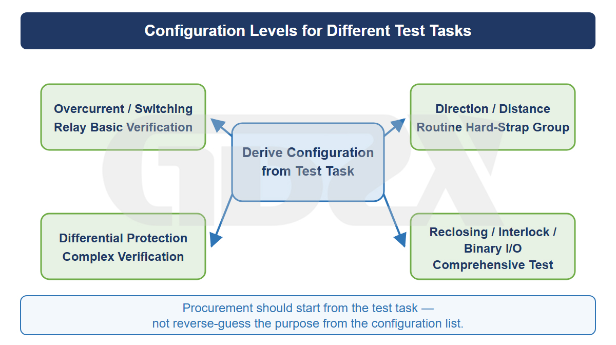
Figure: Configuration Hierarchy Corresponding to Different Test Tasks
5.1 Overview Table
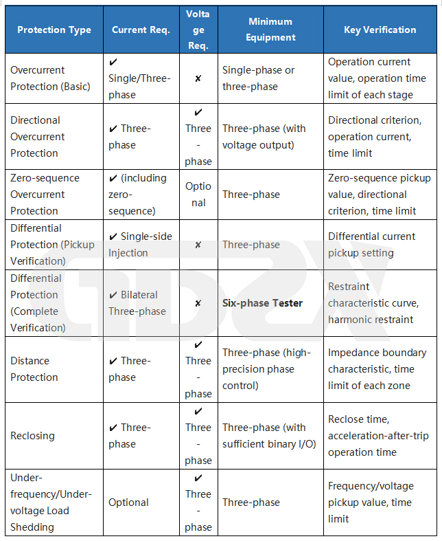
5.2 Overcurrent Protection (including Instantaneous, Time-limited, and Inverse-time)
Overcurrent protection is the most basic and most frequent test item. To help procurement staff understand "what this test actually does," a complete engineering example is given here.
Example scenario: A certain 10 kV feeder protection device has an overcurrent Zone II setting current of 600 A (primary value), operation time 0.50 s, and CT ratio 600/5.
Step 1: Convert to secondary value. This is the prerequisite for all tests —
I_set(secondary) = I_set(primary) ÷ n_CT = 600 ÷ 120 = 5.0 A
The target current the tester should inject is 5.0 A, not 600 A.Failure to convert the primary value to the secondary value is the most common on-site error.
Step 2: Non-operation check. Inject 0.9×5.0 A = 4.5 A for longer than the set time. Expected: protection does not operate.
Step 3: Operation current verification. Slowly raise the current from 4.5 A, increasing by 0.1 A each time. When the protection operates, record the operation current I_act.
Operation error (%) = |I_act - I_set(secondary)| ÷ I_set(secondary) × 100%
Pass reference criterion: operation error ≤ 3% (subject to the device technical specification)
Step 4: Operation time verification. Directly inject 1.2×5.0 A = 6.0 A and measure the protection operation time t_act.
Absolute time error = |t_act - t_set|
Pass reference criterion (typical values):
Setting 0.1~0.5 s → |Δt| ≤ 40 ms or relative error ≤ 3%
Setting >0.5 s → |Δt| ≤ 50 ms or relative error ≤ 3%
Subject to the device technical specification.
Step 5: Repeatability verification. Repeat the same item at least 2~3 times.
Configuration requirement: A single-phase device can complete most overcurrent protection tests. A three-phase device is more efficient. Using six-phase for this kind of test is "using a sledgehammer to crack a nut."
5.3 Directional Protection and Distance Protection
Directional protection must connect both current and voltage.Without voltage, the directional criterion cannot be established and the protection will be blocked and will not operate regardless of how large a current is injected. This is the first item to check for the common on-site problem of "nothing operates no matter what."
Distance protection verification requires precise control of the magnitude and phase of voltage and current to construct a specific impedance value. A complete numerical calculation example is as follows:
Known conditions: Line positive-sequence impedance Z_L = 10 Ω, impedance angle 75°, CT ratio 200/5 (n_CT = 40), PT ratio 110000/100 (n_PT = 1100), Zone I setting ratio n_I = 0.80, reliability coefficient K_rel = 0.85.
Step 1: Primary-side Zone I setting impedance
Z_set.I(primary) = K_rel × n_I × Z_L = 0.85 × 0.80 × 10 = 6.80 Ω
Step 2: Convert to secondary impedance
Z_set.I(secondary) = Z_set.I(primary) × n_CT ÷ n_PT = 6.80 × 40 ÷ 1100 ≈ 0.247 Ω
Step 3: Tester settings
Inject current I = 5.00 A; the corresponding voltage to inject is U = I × Z = 5.00 × 0.247 = 1.24 V
Voltage leads current by angle φ = 75°
Step 4: Verification
Simulated impedance < 0.247 Ω (lower voltage) → protection should operate
Simulated impedance > 0.247 Ω (higher voltage) → protection should not operate
Configuration requirement: A three-phase device is the standard configuration. Distance protection tests have higher accuracy requirements and demand higher voltage accuracy, current accuracy, and phase accuracy from the tester.
5.4 Differential Protection (Transformer Differential, Bus Differential, Line Pilot Differential) — The Core Reason for Six-phase Equipment
Procurement staff do not need to derive the formulas below themselves, but they need to understand one thing: the complexity of differential protection testing is the underlying answer to the question of "similar parameters but very different prices."
The principle of differential protection is to compare the current difference between the two sides of a transformer (or bus, line). During normal operation or external faults, the two-side currents, after being converted by the ratio, have a very small difference; during an internal fault, the difference suddenly increases. During testing, the tester must simultaneously simulate the three-phase currents on both sides (6 currents in total) to construct various combinations of "differential current" and "restraint current" to verify the protection operation boundary.
Specifically, the two core quantities the protection device judges are:
Id = |I1' + I2'| (differential current — fault characteristic; the larger it is, the more likely an internal fault)
Ir = (|I1'| + |I2'|) ÷ 2 (restraint current — larger during external faults, used to "restrain" the protection from maloperation)
The operation logic of the protection device is a "restraint characteristic curve" (typically a three-segment polyline). The general logic is: operate if the differential current is large enough, but if the restraint current is also large (indicating possible through-current from an external fault), a larger differential current is required to operate. The specific parameters (pickup setting Id.min, restraint coefficients K1/K2, knee-point current) are all settings.
Why three-phase equipment cannot do it: Complete restraint characteristic verification requires selecting a dozen or even dozens of operating points on the differential-current vs. restraint-current coordinate plane, injecting two-side currents point by point to depict the protection's actual operation boundary. Each operating point requires simultaneously and precisely controlling the magnitude and phase of 6 currents — one group of 3 simulates the high-voltage side, the other group of 3 simulates the low-voltage side. A three-phase device has only 3 current outputs and physically cannot inject both sides simultaneously.
Why the software must "understand" relay protection: During testing, the tester must also handle the transformer's connection group (e.g., Yd11 corresponds to 30° phase compensation) and the CT ratio conversion of each side (balance coefficient correction) to correctly construct the test currents. If the tester's software templates do not support automatic calculation of the group compensation matrix, the tester must manually compute the six-current parameters for each operating point — a huge workload and highly error-prone.This is why "software depth" is a core indicator for judging a manufacturer's strength.
In addition, there is an easily overlooked test item —harmonic restraint verification. The inrush current generated when a transformer is energized unloaded contains a large amount of second-harmonic (100 Hz); differential protection uses the logic "block when the second-harmonic content exceeds the set ratio" to prevent inrush maloperation. To verify this criterion, the tester must be able to superimpose a specified ratio of second harmonic on the output current, which places specific demands on the tester's waveform synthesis capability.
Configuration requirement summary: Complete differential protection testing (restraint characteristic + harmonic restraint) must use six-phase equipment, and the equipment must support harmonic superposition output and automatic transformer group compensation. Three-phase equipment can only perform simplified differential current pickup setting verification (single-side injection, without verifying the restraint characteristic), which is generally not accepted in formal engineering commissioning.
5.5 Reclosing and Acceleration-after-Trip Test
The complete sequence verified by the reclosing test is as follows:
Step 1 Normal state (HWJ=1, TWJ=0) output normal three-phase current and voltage
Step 2 Switch in fault quantity (current above setting) → start timing
Tester DI acquires protection trip signal → record operation time t1
Step 3 Switch breaker position: HWJ→0, TWJ→1, clear current, start reclosing timing
Step 4 Wait for reclosing setting time t_AR.set
Step 5 Protection issues close command → tester acquires, record t_AR.act
Step 6A (instantaneous fault verification) restore normal current → reclose success ✓
Step 6B (permanent fault verification) apply fault current again → acceleration-after-trip operates → record acceleration-after-trip time t_acc ✓
Key points: The acceleration-after-trip setting limit is usually 0~0.3 s (subject to the device setting). The tester must complete the full sequence of "first trip → breaker open → reclose" before the acceleration-after-trip logic can be triggered.If the reclose step is skipped and a fault is applied directly again, the acceleration-after-trip protection will not operate. This places requirements on the tester's "state sequence" function and the number of binary outputs.
Configuration requirement: A three-phase device (with sufficient binary I/O) can complete most reclosing tests.
5.6 Zero-sequence Protection
Zero-sequence protection uses the sum of the three-phase currents to detect single-phase ground faults. The tester has two methods to simulate zero-sequence current:
Method 1: Three-phase asymmetric injection. Inject fault current Ia only into phase A, set phases B and C to zero; then 3I0 = Ia.
Method 2: Dedicated zero-sequence port output. Some testers provide a dedicated zero-sequence current port that directly outputs 3I0 into the protection device's zero-sequence CT input, with no conversion required.
Configuration requirement: Three-phase device.
6. Applicable Scenarios and Budget Boundaries for Single-phase / Three-phase / Six-phase Equipment
6.1 Single-phase Tester: The "Standard Toolbox" for Basic Calibration
Applicable organizations: County-level power supply companies, rural electrification management stations, small industrial and mining enterprise electrical laboratories, and some 10 kV distribution equipment maintenance teams.
Applicable tasks: Overcurrent protection setting verification (including instantaneous, time-limited overcurrent, inverse-time overcurrent), time relay verification, intermediate relay verification, signal relay verification, and operation/pickup value testing of individual protection elements.
Inapplicable tasks: Directional protection, distance protection, differential protection, complete reclosing sequence verification, and any test requiring simultaneous control of multiphase signals.
Budget range (reference): Domestic mainstream-brand single-phase testers are typically priced in the 10,000~40,000 RMB range, depending on accuracy class, output capacity, and brand premium.
Procurement recommendation: If your organization only manages protection of 10 kV and below distribution lines, and the protection devices are mainly simple three-stage overcurrent protection, a single-phase device is the most cost-effective choice. But do not expect it to "still be usable in the future" — once your scope expands to 35 kV and above, a single-phase device will almost certainly be insufficient.
6.2 Three-phase Tester: The Main Equipment for Medium-scale Organizations
Applicable organizations: Prefecture/city-level power supply company relay protection teams, 35 kV~110 kV substation operation and maintenance units, medium-scale power engineering commissioning companies, and university power laboratories.
Applicable tasks: Covers all capabilities of single-phase equipment, plus: directional protection testing, distance protection (impedance relay) verification, zero-sequence protection testing, three-phase reclosing testing, under-frequency/under-voltage load shedding testing, synchronism check, and simplified differential protection pickup setting verification (with limitations).
Inapplicable tasks: Complete differential protection two-side simultaneous injection testing, bus differential protection joint debugging, simultaneous verification of dual protection sets, and full-function coverage tests required by some type tests.
Budget range (reference): Domestic mainstream-brand three-phase testers are typically priced in the 40,000~150,000 RMB range. Low-end products may have lower accuracy and simple software functions; high-end products have high accuracy, rich automatic test templates, and good software interaction.
Procurement recommendation: The three-phase tester is the most widely applicable model in power systems. For most 35 kV~110 kV level operation, maintenance, and commissioning work, three-phase equipment is fully competent. If your organization occasionally needs to perform differential protection tests, it is advisable to assess the frequency — if it is only a few times a year, it is better to borrow or rent six-phase equipment when needed rather than permanently configuring a six-phase machine for occasional needs.
Core selection principles (summarized from the original):
• Use the most complex typical test scenario as the capability baseline, not the simplest scenario;
• Distribution system mainly at 10 kV → three-phase tester can cover the vast majority of needs;
• Protection devices of different voltage levels (10 kV/35 kV/110 kV) can share the same tester when their CT/PT secondary ratings are the same (usually 5 A or 1 A).
6.3 Six-phase Tester: The "Must-have" for High-end Scenarios
Applicable organizations: Provincial power test research institutes, 220 kV and above substation commissioning units, large power engineering commissioning companies, protection device manufacturers' R&D and type-test laboratories, and power research institutions.
Applicable tasks: Covers all capabilities of single-phase and three-phase equipment, plus: complete transformer differential protection test (two-side simultaneous injection), bus differential protection joint debugging, line pilot differential protection test (with GPS/BeiDou synchronization), simultaneous verification of dual protection sets, full-project coverage of protection type tests, coordination test of auto-reclosing and differential protection, and complex fault sequence simulation (e.g., evolving faults, protection behavior verification during power swings).
Budget range (reference): Domestic mainstream-brand six-phase testers are typically priced in the 120,000~400,000 RMB range, with some high-end models or imported brands exceeding 500,000.
Where does the cost of six-phase equipment come from? This is a question procurement staff often ask. The answer is:
Increased hardware cost: 6 high-precision D/A converters, 6 power amplifiers, and 6 precision current transformer sampling channels — the number of hardware channels doubles, and the cost more than doubles, because the requirements for isolation between the six channels (crosstalk suppression) and synchronization accuracy are extremely high, and the complexity of circuit design and PCB layout grows geometrically.
Synchronization requirements: One of the core selling points of six-phase equipment is the "synchronization accuracy between the two three-phase signal groups" — differential protection testing requires the two-side currents to be strictly frequency- and phase-synchronized, and the inter-channel phase deviation of six-phase equipment is usually controlled within 0.1° or even lower. This accuracy requirement directly raises the cost of the clock circuit, D/A synchronization control, and power-amplifier consistency calibration.
Software cost: The software of six-phase equipment is far more complex than that of three-phase — the differential protection test template must handle many parameters such as transformer group, ratio, balance coefficient, and compensation matrix; the bus protection test template must flexibly configure the bus structure and number of outgoing lines; harmonic restraint verification must support synthesized waveform output. The development and maintenance costs of such professional software are quite high.
Is it worth buying? This question can only be answered against your test task list. If differential protection testing is routine in your work (e.g., more than a dozen transformer differential protection verifications per year), six-phase equipment is a hard requirement and there is no "worth it or not" issue — you have no alternative. If differential protection testing is only an occasional need (e.g., once or twice a year), then the "idle cost" of buying six-phase equipment must be compared with rental costs.
6.4 Priority Ranking When Budget Is Limited — What Must Be Spent and What Can Be Saved
The most common situation in procurement practice is: the technical department wants six-phase high-end, but the budget only approves three-phase mid-range. How to compromise then? The following "priority ranking" is organized according to current procurement decision logic, arranged in three tiers: "must not cut → try not to cut → can compromise":
Must not cut (cutting it makes the equipment a waste):
• The number of phases must meet the most complex rigid test requirements. If your test list includes a "must-do" complete differential protection test, then six-phase is the bottom line; buying three-phase that cannot do it makes it scrap metal. But if the differential protection test can be solved by borrowing or renting equipment, three-phase can fully serve as the daily mainstay.
• The number of binary inputs and outputs must cover the signal count of the most complex test. If this is insufficient, wiring must be repeatedly changed on site each time, and the efficiency loss is continuous. Binary inputs ≥6 and binary outputs ≥4 is the safety line for most scenarios.
• The software must be compatible with the current operating system and have automatic test templates for mainstream protection devices. Poor software usability is the number-one cause of procurement complaints, and software problems usually cannot be completely solved by later upgrades — if the underlying architecture is inadequate, upgrades are just patches.
Try not to cut (cutting it affects test quality but does not make it impossible):
• Output accuracy. Reducing current accuracy from 0.2% to 0.5% has little impact on most overcurrent protection tests, but the impedance boundary test of distance protection is clearly affected. If your main task is overcurrent protection, accuracy can be appropriately relaxed; if you frequently do distance protection, accuracy must not be reduced.
• Phase accuracy. Same logic as above. 0.5° is sufficient for directional protection, but for precise boundary measurement of distance protection, below 0.3° is recommended.
• Harmonic superposition capability. If you do not do harmonic restraint verification for differential protection, this function is unnecessary. But if you buy six-phase equipment, you are likely to do differential protection — then harmonic superposition is a hard requirement and cannot be cut.
Can compromise (affects efficiency or experience but not test results):
• Maximum single-phase current. Reducing from 100 A to 60 A may limit the extreme-current verification of differential instantaneous trip, but is sufficient for most daily tests.
• Timing resolution. Reducing from 0.1 ms to 1 ms has no substantial impact on the vast majority of protection tests.
• The software's automatic report generation and data management functions. These affect efficiency but not the test itself; when the budget is tight, manual report compilation can be accepted.
• Touchscreen vs. pure PC host computer. A touchscreen is convenient but not a necessity.
• Portability and weight. If used mainly in a fixed laboratory, there is no need to pay extra for a lightweight model.
A practical decision case: A certain prefecture-level power supply company had a budget of 150,000 RMB, and the technical department requested six-phase high-end (quoted 280,000 RMB). The final compromise was: buy one three-phase mid-to-high-end unit (100,000 RMB, accuracy 0.2%, 8 binary inputs, complete template coverage) as the daily mainstay, and reserve the remaining 50,000 RMB for renting six-phase equipment during differential protection tests (about 3,000~5,000 RMB per rental, 50,000 RMB enough for 10~15 rentals). If the frequency of differential protection tests indeed rises over the next two years, apply for a special budget to purchase six-phase equipment. This "step-by-step" strategy is far more reasonable than buying one low-end six-phase unit at once (with discounted accuracy and software).


