


NEWSnews
upplier Review, Arrival Acceptance & Procurement Decisions for Relay Protection
10. How to Review Manufacturer Credentials, Software Capabilities, Training and After-Sales Commitments
10.1 How to Judge Whether a Manufacturer Does “Genuine R&D” or “Rebranding and Assembly”
There are many manufacturers of relay protection testers on the market, but few of them truly have core R&D capability. The business model of many small vendors is: purchase core boards from solution providers, make their own enclosure and assembly, pair it with generic software, and sell under their own brand. Such equipment may be 30%–50% cheaper, but causes many problems in long-term use — when the hardware fails, the manufacturer cannot repair it; when the software has bugs, the manufacturer cannot fix them; and when the product generation changes, users have no upgrade path.
How to judge:
R&D team and patents. Genuine R&D manufacturers usually hold relevant invention patents or utility model patents (not only design patents), and their technical staff can clearly explain the core technical principles of the product.
Product iteration history. Genuine R&D manufacturers have clear version iteration records, with definite improvement points in each generation. The “new products” of rebranding assemblers are often just a new enclosure.
Depth of the software. Ask the manufacturer to demonstrate the advanced functions of the software — for example, in the differential protection test template, does it support automatic calculation of the transformer vector group compensation matrix (such as the phase compensation of Yd11)? In the distance protection template, does it support custom impedance characteristic shapes (circle, quadrilateral, polygon)? In harmonic restraint verification, does it support custom harmonic content ratios and phases? Implementing these functions requires a deep understanding of relay protection principles and cannot be achieved by simply copying code.
On-site delivery capability. Require the manufacturer to provide delivery cases of similar projects (preferably verifiable by phone) to find out whether it has a professional on-site commissioning and technical support team. The technical support of a genuine R&D manufacturer can answer questions such as “how to set the transformer vector group in a differential protection test”, while the “technical support” of a rebranding assembler can usually only demonstrate powering on and operating the device.
10.1.1 Framework for Identifying Manufacturer Tiers
Although this article does not recommend or exclude any specific brand, purchasers need a basic understanding of the market landscape. Based on the current industry landscape, relay protection tester manufacturers in China can be roughly divided into three tiers:
First tier (leading manufacturers, 3–5 companies) Characteristics:
• Mature R&D and production systems, with products that have gone through multiple generations of iteration
• Have large-volume delivery records (market presence of hundreds of units or more) at provincial electric power research institutes and large commissioning companies
• Software templates cover all mainstream protection device brands in China and are continuously updated
• Have an independent professional technical support team for relay protection (not a general after-sales hotline)
• Hold measuring instrument manufacturing licenses or relevant qualifications, with a complete metrological traceability system
• Product prices are usually in the upper-middle range among similar configurations
Second tier (regional or niche brands, 10–20 companies) Characteristics:
• Have independent R&D capability, but the product line may be incomplete (e.g., only three-phase, not six-phase)
• Have a good reputation and market share in specific regions or industries
• Software templates cover mainstream protection device brands, but support for niche brands may be insufficient
• Have technical support capability, but the team is small and the response speed may not match the leading manufacturers
• Product prices are usually 15%–30% lower than the first tier, offering good value for money
• Suitable for organizations with limited budgets but with requirements on equipment quality
Third tier (rebranding assemblers, numerous) Characteristics:
• Purchase core boards and power amplifier modules externally, and only make the enclosure, panel, and assembly themselves
• The specification sheets look similar to the first tier (because the core boards may come from the same source), but prices are 30%–50% lower
• Software is usually a generic version with limited templates and weak customization capability
• Have no independent technical support team; after-sales service depends on upstream solution providers
• Product iteration basically relies on changing enclosures, with no capacity for continuous improvement
• Core risk: If the manufacturer transforms or exits the market, the user will face the “three-nothing” dilemma: no spare parts, no software upgrades, and no technical support
How to use this framework: It is not that products from the third tier must never be bought — if your need is only to perform the most basic overcurrent protection setting verification, with low usage frequency and low requirements on software and templates, the low-priced products of the third tier can also be used. However, if your equipment needs long-term, high-frequency use, needs to cover multiple protection types, and needs stable software upgrades and technical support, you should choose at least the second tier or above.
A simple verification method: Give the manufacturer an “application question” — “I have a transformer with a Yd11 vector group; its differential protection uses a device of brand XX, model XX. Please tell me how to set the phase relationship of the tester's currents on both sides during the test.” First-tier technical staff can work it out on the spot or demonstrate with a template; second-tier staff may need to check the documentation but can give the correct answer; third-tier salespeople most likely cannot answer, or reply “let me ask the technical team” and never follow up.
10.2 Key Points for Reviewing Software Capabilities
Installation environment requirements. Confirm the software running environment (operating system version, .NET framework version, driver requirements, etc.) and ensure compatibility with your organization's computer configuration.
Operational stability. Require the manufacturer to continuously run automatic test templates in front of you for at least 2–3 complete test procedures, and observe whether there are crashes, freezes, data loss, or other problems.
Data management capability. Can test data be conveniently exported (Excel/Word format)? Can historical test records be retrieved by protection device number and test date? Is the data backup and recovery mechanism complete?
Remote upgrade support. Can the manufacturer provide a remote software upgrade channel? After an upgrade, will historical data remain compatible?
10.3 Reviewing Training Commitments
Depth of training content. Basic operation training (power-on, wiring, running templates) is only the minimum requirement. Valuable training should include: wiring methods and precautions for various typical protection tests (especially the safe operation procedure of “short-circuit first, then disconnect” on the CT secondary side), the parameter setting logic of automatic test templates (primary value → secondary value conversion), troubleshooting of common faults, and how to interpret and review test reports.
Training mode and duration. Training at the factory or at the user's site? How many days? Are training materials and operation videos provided? Is follow-up online Q&A support available?
Coverage of trainees. If your organization has multiple test engineers, will the training cover all users? Can newly hired employees attend training free of charge later?
10.4 Reviewing After-Sales Service Commitments
Warranty period. Industry practice is usually 1–3 years. Note the difference between “complete-machine warranty” and “core-component warranty”.
Response time. Must be quantified in the contract (telephone response time, remote diagnosis time, on-site service time, and conditions for providing a backup unit).
Spare parts supply commitment. Guaranteed supply period of spare parts after the product is discontinued (no less than 5 years is recommended); prices and supply channels of key wearing parts.
Software maintenance commitment. Free upgrade period, compatibility guarantees after upgrades, and commitments to resolve software adaptation issues caused by operating system upgrades.
Calibration services. Does the manufacturer provide annual calibration services? Does it have metrological traceability qualifications? Are the calibration cost and cycle clearly specified?
11. Acceptance Checklist for Delivery and On-Site Trial
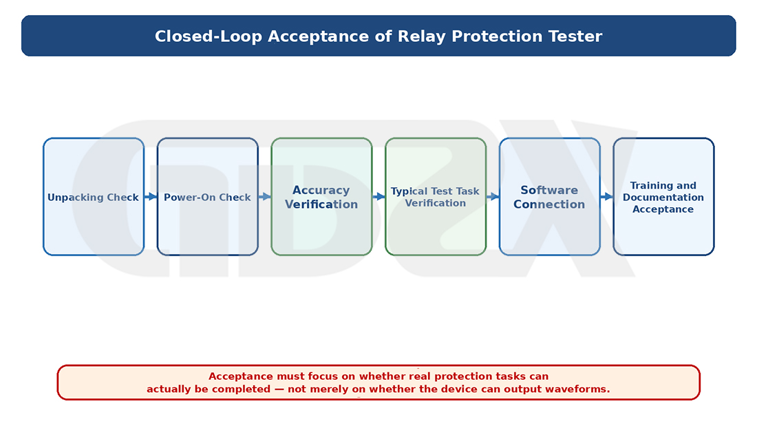
Figure: Closed-Loop Acceptance of the Relay Protection Tester
After the equipment arrives, do not rush to put it into storage. It is recommended to carry out a round of acceptance and trial use according to the following checklist, exposing all problems within the acceptance period.
11.1 Unpacking Inspection
□ The equipment appearance is intact, with no obvious transport damage
□ The nameplate information matches the purchase contract (model, serial number, production date)
□ Check the standard accessories item by item (main unit, power cord, communication cable, test leads, dongle/software USB drive, user manual, factory inspection report, certificate of conformity, metrological traceability certificate)
□ Check optional accessories (if any) item by item
11.2 Basic Power-On Inspection
□ The main unit powers on normally and the software starts without errors
□ Test each output channel one by one: set a known value (e.g., 10 V / 5 A) and verify with an external reference meter whether the deviation between the actual output and the set value is within the nominal accuracy range
□ Verify each binary input channel: use a shorting wire to simulate the protection trip contact signal, and confirm that the software correctly recognizes changes in the binary input state
□ Verify each binary output channel: trigger the outputs from the software, and measure with a multimeter whether the output contacts close/open correctly
11.3 Accuracy Verification
□ Voltage accuracy: at 10%, 50%, and 100% of full scale, verify with a 0.05-class (or better) reference source or a high-accuracy digital meter
□ Current accuracy: verify at 10%, 50%, and 100% of full scale
□ Phase accuracy: output voltage and current with a known phase difference (e.g., set 30.0°) and verify with a phase meter
□ Frequency accuracy: set 50.00 Hz, 45.00 Hz, and 55.00 Hz and verify with a frequency counter
□ Time accuracy: run a test procedure with a known delay (e.g., trigger after 100 ms) and verify with an external timer
11.4 Core Test Function Verification (a protective relay device with known settings is recommended)
□ Overcurrent Protection Automatic Test Template: following the procedure in Section 5.2 above, perform a complete verification of the operating current and operating time, and confirm that the test results are consistent with the protection device settings
□ Directional Protection Test (three-phase or above): set the voltage/current phase relationships for both forward and reverse directions, and confirm that the device judges the direction correctly.Key checkpoint: whether the protection is correctly blocked when no voltage is connected (directional protection without voltage should not operate)
□ Distance Protection Test (three-phase or above): set a known impedance value using the calculation method in Section 5.3 above, and confirm that each zone of the device's distance protection operates correctly
□ Differential Protection Test (six-phase): output two groups of three-phase currents simultaneously using the six phases, and verify the operating threshold and restraint characteristic of the differential protection.Key checkpoint: whether the transformer vector group compensation is handled correctly
□ Harmonic Restraint Verification (six-phase): superimpose the second harmonic and verify whether the harmonic restraint ratio criterion is correct
□ Auto-Reclosing Test: verify that the tester's “state sequence” function can correctly simulate the complete sequence of “fault → trip → reclose → permanent fault → accelerated trip”
□ Automatic Test Report Generation: confirm that an automatic test report can be generated after each test item is completed, and that the report format and content meet requirements
11.5 Software and Compatibility Verification
□ Install the software on the laptop commonly used in your organization and confirm it runs normally
□ USB or network communication is stable and does not disconnect frequently
□ The software runs continuously for more than 2 hours without crashes or memory leaks
□ Test data export works properly (export to Excel and Word formats and open without garbled characters)
11.6 Training and Documentation Acceptance
□ The user manual is complete, and the technical parameter section matches the actual equipment
□ The manufacturer completes the training as agreed in the contract, covering: basic operation, CT secondary-side safety procedures, typical test wiring (including signal flow), use of automatic templates, primary/secondary value conversion, and troubleshooting of common issues
□ Delivery of training materials / operation videos
12. Conclusion: How Purchasers Should Really Make the Decision
Back to the equipment procurement and delivery scenario of 2026, the core conclusion remains: the purchase decision for a relay protection tester is not a process of “choosing a product”, but a process of “matching requirements”. The root of many procurement mistakes lies not in choosing the wrong brand or model, but in not clarifying the requirements before procurement.
Here is the decision process I recommend:
Step 1: List the test tasks. List all relay protection test projects your organization may be involved in over the next 3–5 years, sorted by frequency. This step should preferably be done by the technical backbone of the relay protection team, not by the purchaser alone — because the purchaser may not understand the specific test requirements.
Step 2: Determine the equipment configuration level. Referring to Chapters 5 and 6 above, determine whether single-phase, three-phase, or six-phase equipment is needed based on the test task list, and determine the basic requirements for accuracy, power, and binary inputs/outputs. Core principle: use the most complex typical test scenario as the capability benchmark, not the simplest one.
Step 3: Specify the procurement technical requirements. Organize the 6 core parameters in Chapter 4 and the hidden parameters in Chapter 7 into a technical specification document as the hard threshold for manufacturers' bidding. Do not forget in particular: harmonic superposition capability (when differential protection is involved), the number of binary input/output channels and voltage level matching, and software operating system compatibility.
Step 4: Require on-site demonstrations. Do not rely on paper specifications alone. Require shortlisted manufacturers to bring the equipment to your site for an on-site demonstration,and perform real tests with the protection devices you are actually using. Focus on: whether the automatic test templates are easy to use, whether the wiring logic is clear, whether the test efficiency is satisfactory, and whether the report output is standardized. This step can eliminate most products that “look good on paper but are hard to use in practice”.
Step 5: Review the after-sales service plan. Implement the items in Chapter 10 one by one into the contract terms, especially the after-sales response time limits, software upgrade guarantees, training coverage, and calibration services — these are important components of the total life-cycle cost of the equipment.
Step 6: Do not make acceptance a mere formality. Verify item by item according to the checklist in Chapter 11 and resolve all issues within the acceptance period. Do not find it troublesome — once the acceptance period expires, discovering problems means an entirely different negotiating position.
Purchase decision checklist (one final review):
□ Has the most complex typical test scenario of your organization for the next 3–5 years been defined?
□ Is the single-phase maximum current sufficient for instantaneous differential verification (usually the secondary value corresponding to ≥ 5 times the rated current)?
□ If differential harmonic restraint tests are involved, does the equipment support superposition of at least the 2nd harmonic?
□ Is the number of binary inputs/outputs sufficient for the most complex test project?
□ Does the binary output signal voltage level match the binary input circuits of the on-site protection devices?
□ Is the software compatible with current mainstream operating systems (Windows 10 and above)?
□ Does the software support batch import of settings and standardized report generation?
□ Does the manufacturer have a complete metrological traceability certificate and calibration service system?
□ Is a clear after-sales response time limit specified in the contract?
□ Has a list of in-use protection device models been provided and template support confirmed by the manufacturer?
Finally, about price. A relay protection tester is not a fast-moving consumer good; a service life of 5–10 years per unit is normal. Over the equipment's life cycle, the purchase price is only part of the total cost — if the equipment is hard to use, resulting in low test efficiency; if the templates do not match, forcing manual operation; if unstable software causes rework; or if poor after-sales support leaves the equipment idle — these hidden costs can far exceed the price difference saved at the beginning.
Choose the right one — not the most expensive, nor the cheapest. Choose the one that matches your test requirements.
Appendix: Frequently Asked Questions from Engineering Practice (FAQ)
The following questions are practical issues most frequently asked during on-site delivery. Knowing them helps purchasers better evaluate equipment capability and manufacturer competence.
Q1: The instantaneous (quick-break) protection is set to 0 s — why does the measured operating time come out at tens of milliseconds?
This is normal. The inherent operating time of a microprocessor-based protection = sampling window time (about 20–40 ms) + hardware response time, totaling about 20–50 ms. Setting “instantaneous” only means no additional delay in the protection logic, not physical zero delay. Only exceeding 100 ms requires investigation.
Q2: Should the binary input be connected to the trip output contact of the protection device or to the circuit breaker auxiliary contact?
Connect to the trip output contact of the protection device (the integrated protection trip output), not to the circuit breaker auxiliary contact. Connecting to the circuit breaker auxiliary contact would include the breaker's mechanical operating time (about 30–80 ms), so the measured value does not reflect the operating performance of the protection itself.
Q3: The operating time is normal, but the operating current has a large error — what is the cause?
Troubleshooting order: ① first check whether the CT ratio conversion is correct (failure to convert primary values to secondary values is the most common cause); ② then check whether there is a write deviation in the device settings; ③ finally verify the output accuracy of the tester (consult the calibration certificate).
Q4: Can directional protection be tested with current only?
No. Directional protection must be connected to both current and voltage. Without voltage, the directional criterion cannot be established and the protection will be blocked; no matter how large the injected current is, it will not operate.
Q5: What makes differential protection testing complex?
Mainly three aspects: ① current must be injected from both sides simultaneously with accurate phase compensation (taking into account the transformer vector group and ratio); ② restraint characteristic verification requires multi-point scanning; ③ harmonic restraint verification requires the tester to have harmonic superposition output capability, which an ordinary current source cannot accomplish.
Q6: Can one tester be shared between 10 kV equipment and 35 kV transformer protection?
Absolutely. The tester verifies electrical quantities on the CT/PT secondary side and is independent of the primary system voltage level. As long as the CT secondary rated values (usually 5 A or 1 A) and the PT secondary rated value (usually 57.7 V per phase) of both types of equipment are within the tester's output range, they can share the same tester.
Q7: How often does the tester need calibration?
Refer to the relevant metrological specifications and your organization's metrological management rules (the currently effective provisions shall prevail). Calibration is usually performed once a year; the cycle can be shortened appropriately for high usage frequency or frequent transport vibration.
Q8: The tester indicates the protection has operated, but the circuit breaker did not trip — is it a problem with the protection device?
First distinguish two situations: ① if only functional verification is performed (the circuit breaker is not actually controlled), this is an expected phenomenon — the tester only verifies the protection logic; ② if an overall interlocking test is performed, confirm that the tester's binary outputs have been connected in series into the circuit breaker trip circuit and that the breaker is in the closed state. Protection “operation” and circuit breaker “tripping” are two independent stages and should be verified separately.
Q9: How are the circuit breaker position signals switched during an auto-reclosing test?
Before the fault, keep HWJ=1, TWJ=0 (closed position). Immediately after the protection trips, switch to TWJ=1, HWJ=0 (tripped position) and set the current to zero at the same time, starting the auto-reclosing timer. This switching is usually performed automatically by the tester's sequence — provided that your tester has enough binary outputs to simulate these states.


