


NEWSnews
Relay Protection Test Set Selection Guide: 9 Field FAQs and Testing Standards
Appendix: Frequently Asked Questions in Engineering Practice (FAQ)
The following questions are the practical issues most frequently raised during on-site delivery. Understanding them helps procurement personnel better evaluate equipment capabilities and the technical competence of manufacturers.
Q1: The instantaneous overcurrent protection is set to 0s. Why is the measured operating time several tens of milliseconds?
This is a normal phenomenon. The inherent operating time of a microprocessor-based protection relay = sampling window time (approx. 20~40ms) + hardware response time, totaling approx. 20~50ms. An "instantaneous" setting only means that no additional time delay is added in the protection logic; it does not mean physically zero time delay. Investigation is required only when the value exceeds 100ms.
Q2: Should the binary input be connected to the protection relay trip output contact or to the circuit breaker auxiliary contact?
Connect it to the trip output contact of the protection device (protection relay trip output), not to the circuit breaker auxiliary contact. Connecting to the circuit breaker auxiliary contact includes the mechanical operating time of the circuit breaker (approx. 30~80ms) in the measurement, so the measured value does not reflect the operating performance of the protection itself.
Q3: The operating time is normal, but the operating current error is relatively large. What is the reason?
Troubleshooting sequence: ① first check whether the CT ratio conversion is correct (failure to convert primary values to secondary values is the most common cause); ② then check whether there is a writing deviation in the device setting values; ③ finally verify the output accuracy of the test set (refer to the metrological calibration certificate).
Q4: Can directional protection be tested with current connection only?
No. Directional protection requires both current and voltage to be connected. Without voltage, the directional criterion cannot be established and the protection will be blocked; it will not operate regardless of how large the injected current is.
Q5: What makes differential protection testing complex?
Mainly in three aspects: ① current must be injected from both sides simultaneously with accurate phase compensation (taking into account the transformer vector group and ratio); ② verification of the restraint characteristic requires multi-point scanning; ③ verification of harmonic restraint requires the test set to have harmonic superposition output capability, which an ordinary current source cannot provide.
Q6: Can one test set be shared between 10kV equipment and 35kV transformer protection?
Yes, fully. The test set verifies the electrical quantities on the secondary side of CT/PT, which is independent of the voltage level of the primary system. As long as the CT secondary rated values (normally 5A or 1A) and PT secondary rated values (normally 57.7V/phase) of both types of equipment are within the output range of the test set, they can share one test set.
Q7: How often does the test set require metrological calibration?
Refer to the relevant metrological specifications and the metrological management regulations of the organization (the currently effective regulations shall prevail). Calibration is normally performed once a year; the interval may be shortened appropriately in cases of high usage frequency or frequent transport vibration.
Q8: The test set indicates that the protection has operated, but the circuit breaker has not tripped. Is this a problem with the protection device?
First distinguish between two cases: ① if only functional verification is performed (without actually controlling the circuit breaker), this is an expected phenomenon, as the test set verifies only the protection logic; ② if an overall linkage trip test is performed, confirm that the binary output of the test set has been connected in series into the circuit breaker trip circuit and that the circuit breaker is in the closed position. Protection "operation" and circuit breaker "tripping" are two independent stages and shall be verified separately.
Q9: How is the circuit breaker position signal switched during an autoreclosing test?
Before the fault, maintain HWJ=1, TWJ=0 (closed position). Immediately after the protection trips, switch to TWJ=1, HWJ=0 (open position), reset the current to zero at the same time, and start the autoreclosing timing. This switching is normally completed automatically by the test sequence of the test set and requires no manual intervention — provided that your test set has sufficient binary outputs to simulate these states.
Reference Standards and Regulations
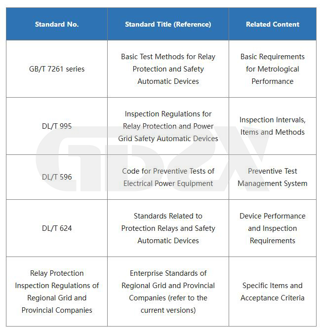
⚠️ The standards listed above may have updated versions or replacement standards. In actual engineering, all test methods, acceptance criteria and inspection intervals shall be based on the currently effective standards and the technical specifications of the corresponding protection devices.
Disclaimer: All technical standards mentioned in this document shall be subject to their currently effective versions. The price ranges, configuration recommendations and reference values for acceptance criteria provided in this document are for industry illustrative reference only; specific procurement decisions shall be made on a comprehensive basis combining actual requirements, budget constraints and market conditions. This document does not constitute a recommendation for, or an exclusion of, any particular brand or model of product.
*This document is technical guidance for general knowledge and procurement purposes and is for reference only. In actual engineering applications, strictly comply with the relevant safety regulations and have the work performed by qualified professionals.*


