


NEWSnews
Relay Protection Test Set Basics: Definition, Testing and Secondary Circuits
Chapter 1 What Is a Relay Protection Test Set
1.1 Definition
A relay protection test set (microcomputer-based relay protection test set, Microcomputer-based Relay Protection Test Set) is a category of specialized secondary test equipment used to perform functional verification, setting checking, and operation logic testing on relay protection devices. Its core capabilities are:
• Outputs simulated current and voltage quantities synchronously with controlled precision, applying them to the secondary input terminals of the relay protection device under test;
• Acquires the digital outputs of the protection device (trip outputs, signal relays, etc.) simultaneously, and measures the operating time precisely;
• Supports complex whole-set coordinated test sequences, verifying the complete secondary circuit logic from protection operation to circuit breaker tripping.
The essence of a relay protection test set: a fault-quantity simulation system, rather than an ordinary current source or voltage source.
1.2 Technical Background of Microcomputer-Based Test Sets
With an embedded computer at its core, it incorporates a high-precision D/A conversion circuit and a power amplification unit to output analog quantities precisely according to the set parameters; it also has built-in timing circuits and digital input acquisition modules to capture the operating time and output status of the protection device. Modern products are mostly equipped with a touchscreen or a PC host-computer interface, with built-in automated test templates for various types of protection tests.
1.3 Four Core Problems Solved by a Single Instrument
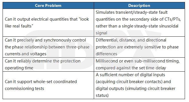
Chapter 2 Significance and Regulatory Basis of Relay Protection Testing
2.1 Why Relay Protection Devices Must Be Tested Periodically
Relay protection devices remain in a "standby" state under normal conditions and go into operation only at the instant a fault occurs in the power system. The characteristic of "inactive for long periods, yet required to operate at critical moments" makes periodic verification of their health status essential.
The two extremes of fault consequences:
• Failure to trip: the breaker should trip but does not; the fault current persists, which may cause equipment damage or even fire;
• Unwanted tripping: the breaker trips when it should not, causing unnecessary power outages and compromising the reliability of power supply.
2.2 Regulatory Status and Reference Standards
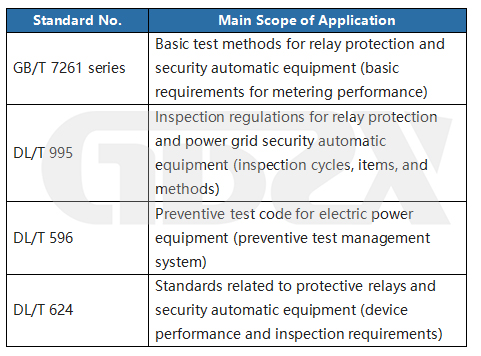
⚠️ The above standards may have been updated to newer versions; in actual engineering practice, please consult and confirm the currently valid versions.
Chapter 3 Relationship Between the Test Set and the Secondary Circuit
3.1 Overall Architecture of the Secondary Circuit
CT primary side → CT secondary circuit → current input terminals of the protection device
PT primary side → PT secondary circuit → voltage input terminals of the protection device
Protection device trip output → circuit breaker trip coil → circuit breaker opens
Circuit breaker auxiliary contacts (TWJ/HWJ) → feedback to the protection device
Test set connection point: between the CT/PT secondary side and the input terminals of the protection device, injecting simulated fault quantities directly without affecting the operation of the primary system.
3.2 Flow Directions of the Four Key Signals
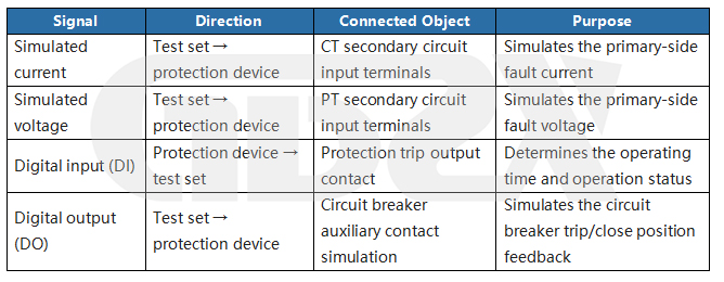
3.3 Safety Operating Procedures
⛔ Safety Warning (Must Read): The CT secondary circuit must never be left open. Correct operating sequence: 1. First short-circuit the CT secondary side reliably (short-circuit at the CT terminal block side); 2. Then disconnect the circuit between the CT and the protection device; 3. Connect the test set to the current input terminals of the protection device; 4. After the test is completed, first restore the connections, then remove the short-circuiting links. An open CT secondary circuit will generate dangerously high voltage, which may cause personal injury or equipment damage.


