


NEWSnews
Precision Phase Measurement in Power Systems: The SMG2000E Double Clamp Digital
Introduction
In power system commissioning, protection testing, and energy metering verification, accurate phase-angle measurement between voltage and current signals is critical. Mismatched phase relationships can indicate incorrect transformer wiring, reversed CT polarities, or faulty differential protection loops. The SMG2000E Double Clamp Digital Phase Meter addresses these on-site challenges with a dual-channel, handheld design that combines high resolution, wide dynamic range, and intuitive operation—all without breaking the circuit.
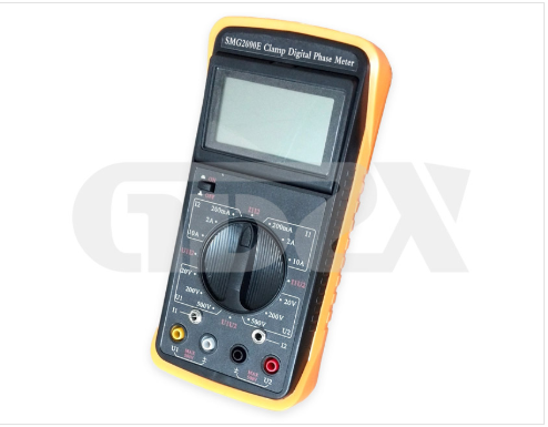
This article reviews its technical architecture, performance specifications, and practical application boundaries, providing engineers and field technicians with a clear reference for integrating this instrument into routine testing workflows.
Core Measurement Capabilities
The SMG2000E supports three fundamental phase combinations:
U–U (voltage-to-voltage)
I–I (current-to-current)
U–I (voltage-to-current)
This flexibility allows technicians to:
Identify inductive vs. capacitive loads via phase angle sign.
Determine the phase sequence of three-phase voltage systems.
Verify transformer vector groups and bus differential protection CT groups.
Check watt-hour meter wiring correctness.
The instrument operates over a phase range of 0°–360° with a resolution of 1° and a basic intrinsic error of ±2° under reference conditions—sufficient for most relay and metering applications.
Electrical Specifications and Accuracy
Voltage Measurement
Range | Resolution | Intrinsic Error (RD + Range) |
20 V | 0.01 V | ±(0.3% + 0.2%) |
200 V | 0.1 V | ±(0.3% + 0.2%) |
500 V | 1 V | ±(0.3% + 0.2%) |
Common-mode input impedance: 2 MΩ (all ranges)
Phase-test voltage input impedance: >500 kΩ
U1–U2 phase-measurement loop impedance: 40 kΩ (dedicated low-impedance path for stable phase reference)
Current Measurement
Range | Resolution | Intrinsic Error (RD + Range) |
200 mA | 0.1 mA | ±(0.3% + 0.2%) |
2 A | 1 mA | ±(0.3% + 0.2%) |
10 A | 10 mA | ±(0.3% + 0.2%) |
The clamp jaws (Ø7 mm × 9 mm) incorporate a patented low-current design, achieving a current resolution down to 0.1 mA—a key advantage for testing low-level secondary CT circuits without range switching between 10 mA and 10 A.
Operating Conditions and Error Budget
The instrument’s intrinsic error is defined under base conditions:
Ambient temperature: 23°C ± 2°C (typical, per industry standard)
Ambient humidity: 40%–60% RH
Signal waveform: sinusoidal (distortion <1%)
Signal frequency: 50/60 Hz ± 1%
External electromagnetic field: <1 mT
Conductor position centered in clamp jaw
When any of these influence quantities deviate within the rated operating range, the limits of rated working error shall not exceed twice the intrinsic error limits. This 2× safety margin is crucial for field use, where temperature, harmonics, and conductor placement are rarely ideal. Technicians should therefore interpret field readings with this expanded uncertainty in mind, especially when measuring near thresholds (e.g., 10 mA or 3 V).
Mechanical and Power Design
Parameter | Specification |
Display | 3½-digit LCD, 25 mm character height, 70° viewing angle |
Sampling | 3 readings/second |
Power | Single 9 V laminated battery, consumption <5 mA |
Meter size | 192×95×55 mm³, 280 g |
Clamp size | 140×42×20 mm³ each, 200 g each |
Storage | –10 °C to +50 °C |
The handheld form factor, rotating function switch for voltage/current/phase readout, and high-contrast display facilitate single-operator use in cramped switchgear cabinets. The low power consumption also includes a battery-voltage test function—a practical feature to prevent unexpected shutdown during critical measurements.
Practical Application Notes
No circuit disconnection – The clamp-on current probes and high-impedance voltage inputs allow live testing without interrupting service, reducing outage risk.
Phase-sequence checks – By measuring U–U phase angles on a three-phase system, the user can verify ABC or ACB sequence within seconds.
Differential protection verification – The dual-channel input enables direct comparison of CT secondary currents from different bus sections, revealing phase disparities that indicate wiring errors or saturation effects.
Low-current resolution – The 0.1 mA resolution is particularly useful for testing standby CT circuits or leakage paths where conventional clamps (1 mA resolution) are inadequate.
Limitations and Best Practices
The phase accuracy (±2°) is specified for sinusoidal signals; heavily distorted waveforms (e.g., from VFDs or rectifiers) may introduce additional errors.
For U–I phase measurement, the voltage must be ≥10 V and current ≥10 mA to remain within the rated working range; outside these boundaries, the error multiplier may exceed 2×.
Ensure the conductor is centered in the clamp jaw to minimize position-induced error (specified under base conditions).
Store the instrument within –10 °C to +50 °C to avoid LCD degradation or battery leakage.
Conclusion
The SMG2000E offers a balanced trade-off between portability, resolution, and cost for on-site phase-angle diagnostics. Its dual-clamp architecture, wide current/voltage spans, and clear error limits make it a reliable tool for substation commissioning, transformer testing, and revenue-meter verification. By understanding its intrinsic accuracy, working-error expansion factors, and mechanical constraints, power engineers can effectively incorporate it into both routine and fault-diagnostic procedures—ensuring that phase relationships remain a controlled, not guessed, parameter in the power network.
GDZX is a manufacturer of power detection equipment, offering a diverse range of products with comprehensive models and providing professional technical support. Contact us at +86-27-6552607 or +86-17396104357.Website: http://en.gdzxdl.com/


