


NEWSnews
How to Configure a Benchtop PD Detector: Specs, Applications & Budget Tiers
4. Key Parameters to Consider When Purchasing a Benchtop Partial Discharge Detector (with a Typical Parameter Table)
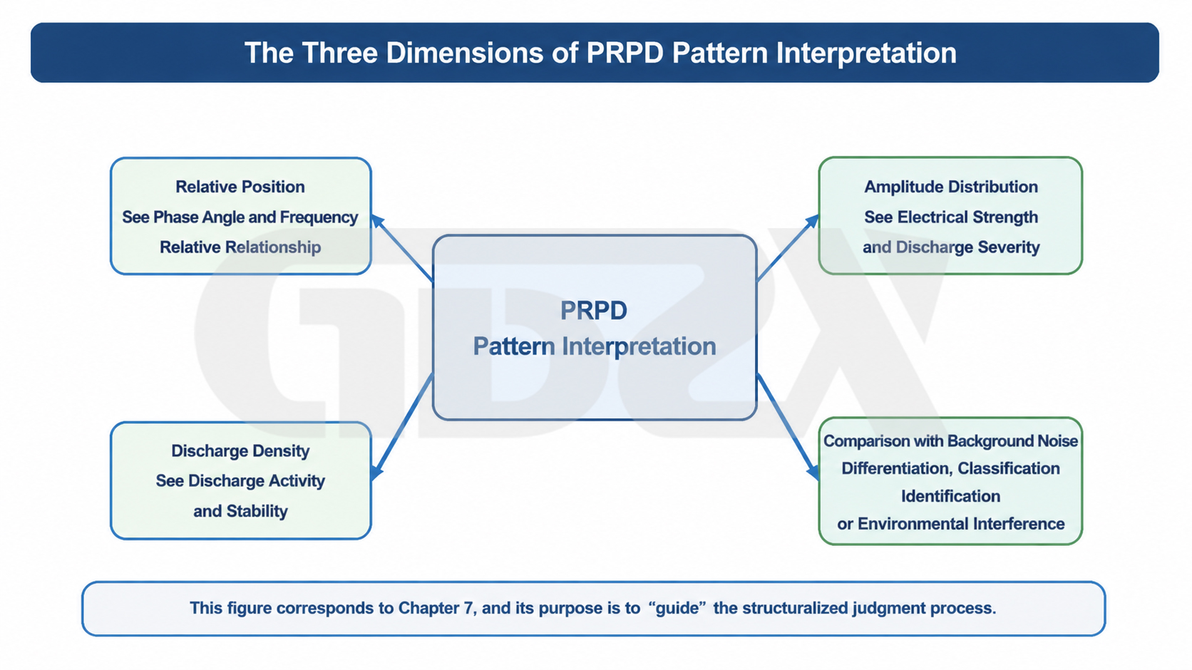
Figure: Key Evaluation Dimensions of PRPD Pattern Analysis
Start with a typical parameter table for benchtop partial discharge detectors (based on identifiable information from reference images and commonly specified industry ranges; actual specifications should always be confirmed against the specific configuration and the manufacturer’s technical documentation). Then, break down each parameter to explain how to interpret it and what to look for when selecting and purchasing a device.
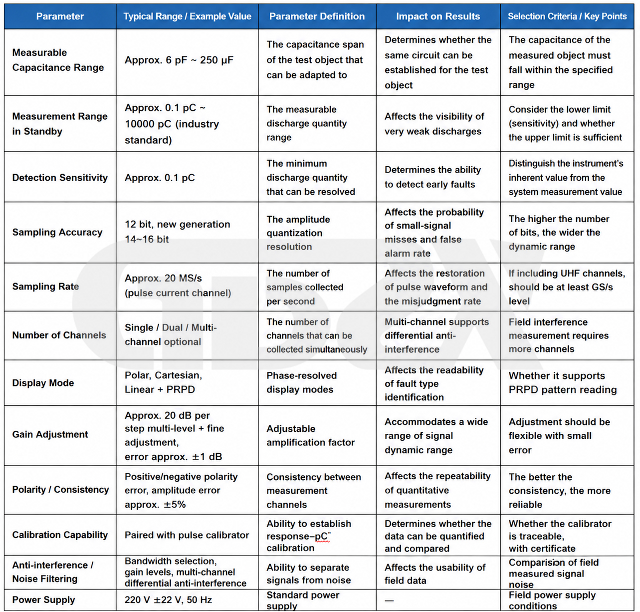
Below, we break down the most critical parameters.
4.1 Detection Sensitivity — Two Key Indicators You Must Distinguish
Sensitivity determines how early a defect can be detected, but one of the most common pitfalls when purchasing a device is that sensitivity has two distinct levels:
1.Intrinsic Instrument Sensitivity: The smallest signal that the instrument itself can resolve. This is typically the sensitivity value specified in the technical parameter table.
2.System Measurement Sensitivity: The actual sensitivity of the complete measurement circuit, including the coupling capacitor, measuring impedance, cables, and other components. This is the sensitivity that matters in real-world testing.
Procurement Benchmark: A system measurement sensitivity of approximately 0.1 pC represents a mainstream mid-to-high-end level for benchtop quantitative measurements.
Procurement Reminder: Ask the manufacturer to clarify whether the stated sensitivity refers to intrinsic instrument sensitivity or system measurement sensitivity, and request the test conditions, including background noise level and coupling capacitor configuration.
Prioritize Based on the Application: For laboratory testing of low-capacitance, low-noise objects such as small instrument transformers and bushings, sensitivity is a key consideration. For testing in high-interference environments, noise immunity and interference rejection become more important. Avoid making a blanket statement that “noise immunity is always more important than sensitivity.”
4.2 Test Object Capacitance Range — Determines Whether the Device Can Measure Your Test Objects
The measurement circuit response of the pulse current method is closely related to the capacitance of the test object. If the specified range is too narrow, certain test objects may be difficult or impossible to measure accurately.
Procurement Benchmark: A capacitance range of approximately 6 pF to 250 μF provides relatively broad coverage, from pF-level bushings and instrument transformers to μF-level cables, large windings, and capacitors.
Procurement Reminder: Before purchasing, prepare a capacitance list of all test objects and confirm that each one falls within the specified measurement range.
Exceeding the specified range does not necessarily mean the device cannot be used. For high-capacitance test objects such as large cables, an external matching or buffer impedance may be used to accommodate the measurement. Ask the manufacturer to clarify the available solution rather than simply assuming that a test object outside the nominal range cannot be measured.
4.3 Sampling Resolution and Sampling Rate — Determining How Clear the Evidence Chain Is
Sampling resolution (12-bit / 14–16-bit) → amplitude-domain resolution → whether small signals can be distinguished from larger signals → risk of missed defects
Sampling rate (approximately 20 MS/s for the pulse current channel) → time-domain reconstruction capability → whether nanosecond-level pulse waveforms are accurately captured or flattened → risk of misjudgment
Procurement Benchmark: 12-bit sampling resolution is widely used, while newer-generation systems commonly offer 14–16-bit resolution. For the pulse current channel, a sampling rate of approximately 20 MS/s is a common benchmark.
Procurement Reminder: If the instrument includes a UHF channel, do not use 20 MS/s as the benchmark for UHF performance. UHF measurements require GS/s-level sampling, so the specifications should be verified separately for each channel.
4.4 Number of Channels and Noise Immunity — A Key Differentiator for Field Usability
Multiple channels are not simply about how many measurement points can be connected. More importantly, one channel can be used as a reference for differential measurement to suppress common-mode interference.
Field noise is often present across multiple measurement points, whereas genuine partial discharge is typically localized. This difference is precisely where effective noise rejection can be achieved.
Procurement Benchmark: Look for features such as selectable frequency bands, multiple gain settings, and multi-channel differential measurement.
Procurement Reminder: Noise immunity is one of the most difficult capabilities to evaluate from a specification sheet, yet it can have a major impact on real-world performance. Actual signal-to-noise ratio (SNR) testing in a representative field environment is essential—do not rely solely on test results from shielded environments.
Variable-frequency drive interference and wireless signals can produce interference patterns that resemble partial discharge. A key consideration is whether the software can distinguish these interference sources—for example, variable-frequency interference may appear as a relatively uniform distribution, while wireless noise generally lacks phase correlation.
4.5 Pattern Analysis Capability — The Core of Defect-Type Identification
Pattern analysis is what enables the transition from determining “whether partial discharge exists” and “how strong it is” to determining “what type of discharge it is.”
Elliptical, sinusoidal, and linear phase displays are classic visualization methods for the pulse current method, while PRPD (Phase-Resolved Partial Discharge) analysis is a primary tool for discharge pattern identification.
Procurement Reminder: During an on-site demonstration, put the software to the test with representative defect patterns. For example, discharge from free metallic particles may exhibit a voltage-threshold jump, a sharp increase in discharge magnitude after voltage is raised, and residual discharge after the voltage is reduced.
Corona discharge in air and corona discharge in oil can also exhibit significantly different phase distributions. The key question is whether the software can clearly display these characteristics and provide useful assistance in defect identification.
A device with weak pattern-analysis capabilities may be able to detect partial discharge, but it may not be able to effectively identify the underlying defect type.
4.6 Calibration Capability — The Foundation of Comparable Quantitative Data
The apparent charge is defined in GB/T 7354-2018 as the equivalent transferred charge at the terminals of the test object.
For a purely capacitive test object without a voltage-divider structure, the apparent charge is approximately equivalent to the actual charge transferred by the defect. For defects involving solid insulation voids, floating electrodes, or surface discharge, however, the relationship with the actual defect charge can differ.
Regardless of the defect type, uncalibrated readings should not be treated as comparable quantitative data or used directly in formal test reports.
Procurement Reminder: The calibration relationship q₀ = C₀ × U₀ applies only to step-voltage pulse calibrators. It does not apply to AC calibration or charge-injection calibration methods.
When testing long, large-capacitance cables—particularly cables several hundred meters in length—wave propagation effects must also be considered. A single-end calibration may not accurately represent the sensitivity of the entire cable. Ask the manufacturer to clearly explain its cable calibration and measurement-sensitivity verification method.
For quantitative partial discharge measurements, the system should include a suitable calibrator, provide traceability, and support the issuance of calibration certificates.
5. What Configuration Is Best Suited to Different Test Objects and Applications?
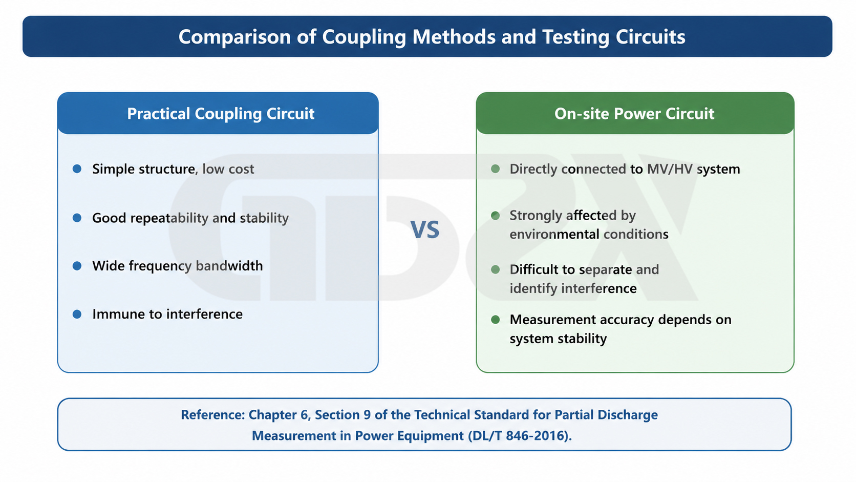
Figure: Differences Between Quantitative Testing and Online Screening Workflows
Benchtop partial discharge testing is primarily focused on de-energized quantitative measurements, but the optimal configuration can vary depending on the specific test object and application.
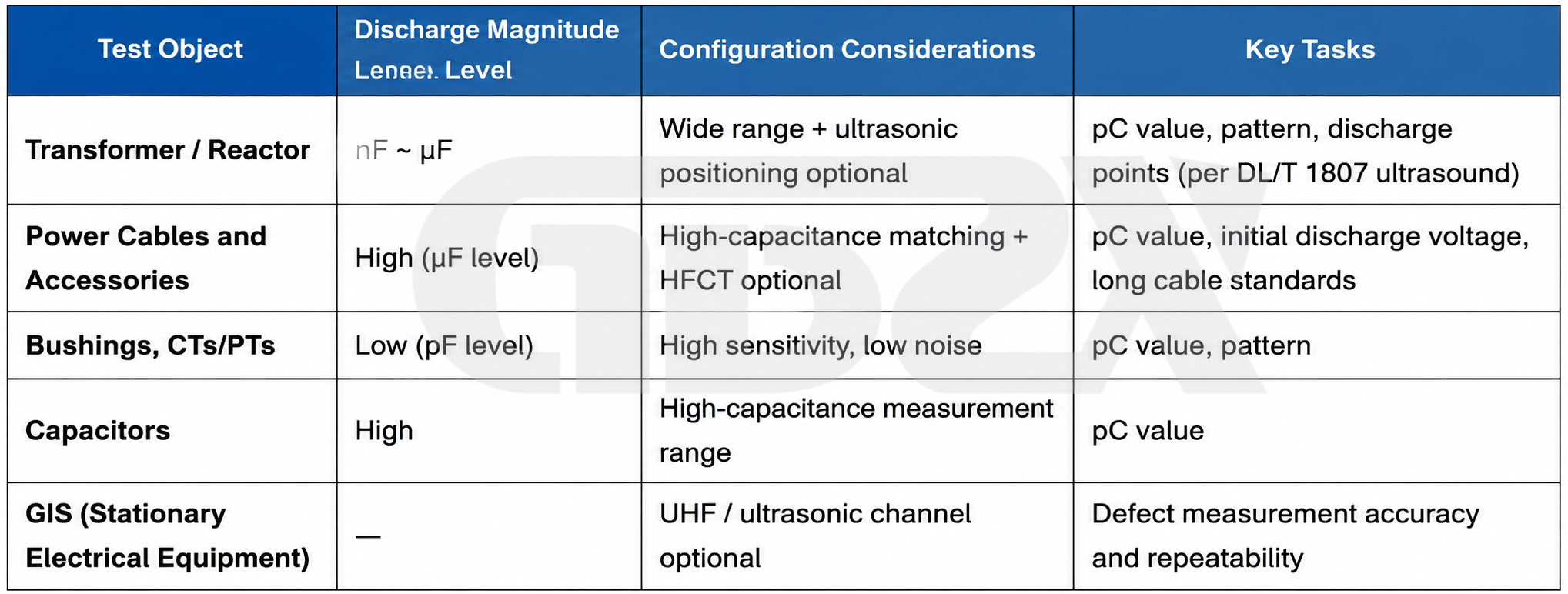
Configuration Matching Logic:
1.Wide range of test-object capacitance (e.g., both bushings and cables) → Choose a system with a wide capacitance range, such as approximately 6 pF–250 μF.
2.Primarily low-capacitance test objects (e.g., bushings and instrument transformers) → Prioritize high sensitivity and low noise.
3.Frequent cable testing → Pay particular attention to high-capacitance test-object compatibility and long-cable calibration methods, and consider adding an HFCT (High-Frequency Current Transformer).
4.Need to locate the discharge source → Add ultrasonic localization capability.
6. 6. Configuration Tiers and Budget Boundaries
The price ranges provided are illustrative industry references only. Actual prices can vary significantly depending on the configuration, brand, and market conditions. They are intended only to provide a general indication of the budget level; actual pricing should be confirmed through quotations from manufacturers or suppliers.
Priority Ranking When Budget Is Limited:
Never Cut — Cutting These Features Defeats the Purpose of the Purchase:
1.Calibration and Traceability — Without them, pC readings cannot be reliably used in formal test reports.
2.Noise Immunity — If the instrument cannot perform reliably in the field, its practical sensitivity is effectively reduced.
3.System Measurement Sensitivity — What matters is the actual sensitivity of the complete measurement system, not simply the instrument’s nominal intrinsic sensitivity.
Avoid Cutting — These Features Affect Measurement Quality:
1.Sampling Resolution and Sampling Rate — Critical for accurate discharge pattern identification.
2.PRPD Pattern Analysis Depth — Important for identifying and distinguishing different defect types.
3.Number of Channels — Particularly important in high-interference testing environments.
Can Be Compromised — These Features Mainly Affect Efficiency and User Experience:
1.Automatic report generation
2.Touchscreen operation vs. PC-based software
3.Portability
4.Extended capacitance ranges beyond the requirements of your actual test objects


