


NEWSnews
Benchtop Partial Discharge Detector Procurement, Selection, and Acceptance Guide
7. Recommended Approaches for Common Procurement Scenarios
Scenario 1: Power Testing Organizations / Third-Party Testing Laboratories (primarily requiring quantitative results and formal reports) Recommendation: A mainstream diagnostic benchtop unit with multiple channels, system measurement sensitivity of approximately 0.1 pC, calibration traceability, PRPD pattern recognition, and verified interference resistance. For cables, HFCT is often added; for transformers, ultrasonic positioning is recommended. These are core users of benchtop PD equipment, so essential capabilities should not be compromised.
Scenario 2: Substation Maintenance and Testing Teams (inspection follow-up + commissioning and handover tests) Recommendation: A mainstream diagnostic benchtop unit, with particular emphasis on interference resistance—because substation environments can be highly noisy—and PRPD pattern recognition. A handheld unit can be added for routine inspections, with the two devices serving different roles.
Scenario 3: Equipment Manufacturers — R&D / Quality Inspection Recommendation: A high-spec laboratory model, focusing on high sensitivity, 14–16-bit acquisition, advanced pattern-recognition capabilities, standardized batch measurement, and data management.
Scenario 4: Universities / Research Laboratories Recommendation: A mainstream to high-spec model, focusing on user-friendly PD pattern visualization for teaching, real-time waveform/vector display, step-by-step manual operation, and expandability.
Scenario 5: Organizations with Occasional Quantitative Testing Needs Note: If quantitative testing is performed only a few times per year, evaluate outsourced testing or rental of benchtop equipment versus purchasing. There is no need to maintain a high-spec benchtop system for low-frequency requirements.
8. Common Procurement Pitfalls
Pitfall 1: Comparing only sensitivity figures while overlooking system sensitivity and interference resistance. A specification may look impressive, but performance can deteriorate after the coupling capacitor and cables are connected and the equipment is used in the field. How to avoid it: Require the supplier to provide system measurement sensitivity and test conditions, and verify the signal-to-noise ratio under real operating conditions.
Pitfall 2: Purchasing quantitative equipment without calibration or traceability. The pC readings may not be comparable or suitable for reports; alternatively, a step-pulse calibration formula may be incorrectly applied to AC calibration. How to avoid it: Specify in the contract that a calibrator is included, is traceable, and is supplied with a certificate; clarify calibration methods for special test objects such as cables.
Pitfall 3: Weak PD pattern-recognition software that cannot identify defect types. If the software only displays amplitude, it cannot identify defect types or distinguish interference. How to avoid it: Demonstrate PRPD and use characteristic patterns such as free particles (voltage-threshold jumps, sudden increases during voltage rise, residual activity during voltage reduction), corona, and other known features for verification.
Pitfall 4: Ignoring the coupling capacitor's own partial discharge in parallel coupling. PD generated by Ck is directly superimposed on the measurement result. How to avoid it: Prioritize the PD level of Ck during selection and require a low-PD coupling capacitor. The series method (measuring impedance connected in series with the test object to ground) also has advantages in suppressing oscillations for long cables and high-capacitance test objects, so the coupling method should be selected according to the application.
Pitfall 5: Using outdated or mismatched sampling specifications. For example, treating 12-bit acquisition as high-end or using 20 MS/s to evaluate a UHF channel. How to avoid it: Recognize that 14–16-bit acquisition is common in newer systems; evaluate sampling rates by channel, and UHF channels require GS/s-level sampling.
Pitfall 6: Misunderstanding the measurement range. A test object whose capacitance exceeds the nominal range is not necessarily impossible to measure. How to avoid it: For large-capacitance cables and similar objects, an external matching buffer impedance may be used. Ask the supplier to clarify the available solution.
Pitfall 7: Overlooking safety pre-checks and supporting accessories. High-voltage circuits require insulation checks and a withstand-voltage pre-check of the coupling capacitor; the coupling capacitor and calibrator must match the test object. How to avoid it: Require a list of standards and optional accessories, confirm compatibility, and include the required safety pre-check items.
Pitfall 8: Overlooking metrological calibration requirements. Benchtop PD equipment is precision measurement equipment and generally requires periodic calibration. How to avoid it: Confirm the supplier's metrological traceability qualifications, annual calibration service, and service cost cycle.
9. How to Evaluate Supplier Documentation, Software Capabilities, and After-Sales Support
9.1 Genuine R&D vs. OEM/Private-Label Assembly
Private-label suppliers often purchase core circuit boards externally and rebrand generic software. Their prices may be 30%–50% lower, but their pattern-recognition capabilities are often weaker, interference resistance is poorer, and upgrade paths may be unavailable. Evaluation methods:
• Evaluate software depth: Can it distinguish free particles (voltage-threshold jumps, sudden increases during voltage rise, residual activity during voltage reduction), air corona vs. corona in oil, and interference (uniform frequency-converter distribution, wireless interference with no phase correlation)?
• Evaluate calibration and traceability: Can the supplier clearly explain the definition of apparent charge (equivalent transferred charge at the two terminals of the test object), applicable calibration conditions, and whether it has metrological qualifications?
• Evaluate actual interference resistance: Demonstrate that genuine PD can be identified in an interference-rich environment.
• Check delivery references: Can comparable deliveries be verified by phone, and can the technical support team answer questions such as, “What defect does this PRPD pattern represent, and how should it be identified?”
9.2 Supplier Tiers (for Evaluation Only; No Specific Brands Recommended)
Tier 1: Strong pattern-recognition capabilities, metrological traceability, an independent PD technology team, a track record of batch deliveries, and mid-to-high pricing.
Tier 2: In-house R&D but an incomplete product line, good regional reputation, and strong cost performance (15%–30% lower pricing).
Tier 3: Private-label assembly, specifications that look competitive but weak software, no independent technical support, and a risk of leaving the market without support.
Verification method: Give the supplier an application question such as, “What defect does this PRPD pattern represent, and how should it be identified?” Tier 1 suppliers should be able to explain the pattern-recognition logic on the spot; Tier 3 suppliers will often be unable to provide a satisfactory answer.
9.3 Software and After-Sales Evaluation
• Software: Real-time PRPD display, data storage and playback, trend comparison, data export, operating-system compatibility, and stable continuous operation.
• After-sales support: Quantified response times; accessory supply periods for coupling capacitors, calibrators, and other components; free upgrade period; annual metrological calibration service and traceability qualifications.
• Training: Circuit setup and calibration, coupling capacitor selection, pattern interpretation, defect identification, interference suppression, and report interpretation—covering all users.
10. Incoming Acceptance and On-Site Trial Checklist
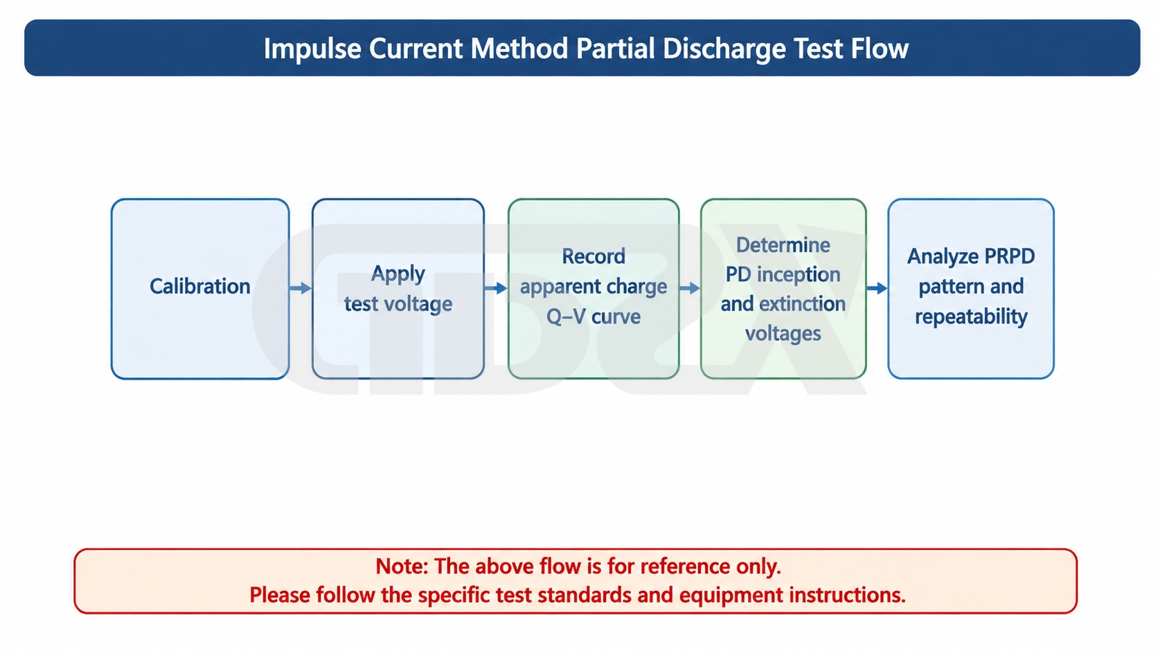
Illustration: Typical Benchtop PD Test and Acceptance Process
10.1 Unpacking Inspection
1. Verify that the equipment is undamaged and that the nameplate matches the contract (model, serial number, date).
2. Check all standard accessories item by item (main unit, coupling capacitor, measuring impedance, calibration pulse generator, test cables, software/dongle, user manual, factory inspection report, certificate of conformity, metrological traceability certificate).
3. Verify that the coupling capacitance is compatible with the test object.
10.2 Calibration and Sensitivity Verification
1. Use a step-pulse calibrator to inject a known charge (e.g., q0 = C0 × U0 = 100 pF × 2 V = 200 pC) and confirm that the reading matches the injected value.
2. Inject a small charge close to the specified sensitivity at the low range and confirm that it can be resolved; record the background-noise conditions.
3.Recalibrate after changing the test object or coupling capacitor and confirm that the reading is correct.
10.3 Core Function Verification (using known PD samples or a standard PD source)
1. Quantitative measurement: Apply a known PD level and confirm that the pC reading is stable and repeatable.
2.PRPD pattern: Confirm real-time display of phase, amplitude, and repetition rate, with a clear pattern.
3. Defect identification: Use different types of PD samples to determine whether the patterns can assist with defect identification.
4.Interference verification: Measure in an interference-rich environment and verify whether multi-channel differential measurement/filtering can suppress interference and provide a usable signal-to-noise ratio.
5. Inception/extinction voltage: Confirm that the system correctly records the values during voltage increase and decrease.
6.Report generation: Confirm that standardized reports can be generated automatically.
10.4 Software and Documentation
1.Install and run the software on the computers commonly used by the organization; verify stable communication and two hours of continuous operation without abnormalities.
2.Verify normal data export (no garbled characters in Word/Excel files).
3. Verify that the user manual is complete and that the specifications match the actual equipment.
4.Confirm that the supplier has completed training (circuit setup/calibration/patterns/defect identification/reports) and provided training materials.
11. Conclusion: How Procurement Personnel Should Actually Make the Decision
Returning to the 2026 context of PD testing and equipment delivery, the core conclusion remains: purchasing a benchtop PD system is not about choosing the one with the highest sensitivity, but choosing one that can quantify, interpret, and match your test objects. “Being able to measure” is only the entry requirement; “being able to identify” is where the value lies. The gap between the two—system sensitivity, interference resistance, pattern recognition, and calibration traceability—is a major source of price differences.
Decision Process:
1. Define the test objects and tasks: What objects will be tested (capacitance range)? Are pC reports required? Is defect identification required? This should be determined by the technical lead.
2. Confirm the benchtop approach: If quantitative measurement, defect identification, verification, and formal reporting are required, a benchtop system is essential. If the task is only energized inspection, a handheld device is more appropriate.
3. Define the technical requirements: Core parameters (system sensitivity, capacitance range, sampling resolution/rate, channels, PRPD) + calibration traceability + verified interference resistance.
4. Require a demonstration under real conditions: Use your test object in your interference environment to evaluate interference resistance and pattern recognition—eliminate products that can measure but cannot interpret.
5. Evaluate total life-cycle cost: After-sales support, upgrades, annual calibration, coupling capacitor/calibrator accessories, and training.
6. Do not treat acceptance as a formality: Verify each item according to Section 10.
Procurement Decision Checklist:
1. Have you defined the capacitance range of the main test objects and the required tasks (quantification/defect identification)?
2. Is the stated sensitivity the system measurement sensitivity or only the instrument's intrinsic sensitivity?
3. Is the capacitance of the test object within the measurement range (e.g., approximately 6 pF–250 μF), and is there a matching solution for objects beyond the range?
4. Is the sampling resolution at the current generation level (14–16 bit), and has the sampling rate been confirmed for each channel?
5. Is a step-pulse calibrator included, is it traceable, and is a certificate provided, including calibration solutions for special objects such as cables?
6. Does the system provide PRPD patterns, defect-type identification, and interference discrimination?
7. Does the PD level of the coupling capacitor Ck meet requirements (parallel method)?
8. Has interference resistance been verified under real operating conditions?
9. Does the contract specify after-sales response, metrological calibration service, and accessory supply?
Choose equipment that can interpret and that matches the test object—not the product with the most impressive numbers on the specification sheet.
12. Frequently Asked Questions on Procurement and Selection
Q1: Why can't the procurement of a benchtop PD system be based only on price and sensitivity figures? The price difference mainly comes from capabilities that are not immediately visible—system sensitivity, interference resistance, pattern recognition, and calibration traceability. Sensitivity is only the upper limit of capability; whether that capability can be realized depends on interference resistance and the actual operating environment. A low-cost system that cannot identify defects, produces incomparable data, or cannot generate compliant reports may create hidden costs far exceeding the initial savings.
Q2: How should the procurement boundary between benchtop and handheld PD equipment be defined? For quantitative measurement, defect identification, verification, and formal reporting → benchtop; for inspection, initial screening, portability, and coverage → handheld. Many organizations use both: the handheld unit identifies suspicious conditions, while the benchtop system determines the actual condition. Handheld measurements are relative values and cannot replace the calibrated pC measurement of a benchtop system.
Q3: How do sensitivity, sampling resolution, sampling rate, and multi-channel capability affect procurement decisions? System sensitivity determines how early a defect can be detected, but must be evaluated together with interference resistance and field usability. Sampling resolution and sampling rate determine waveform fidelity and the probability of misidentification; they are critical for defect identification. Note that 14–16-bit acquisition is typical of newer systems, while UHF channels require GS/s-level sampling. Multi-channel capability determines field interference resistance. None of these should be compromised for quantitative diagnostics.
Q4: Why is there such a large price difference between benchtop PD systems, and where does the difference mainly come from? The main differences are system measurement sensitivity, interference suppression and filtering, sampling capability, PRPD visualization and pattern-recognition software, calibration traceability, and after-sales training. Capacitance and sensitivity may look similar on a specification sheet, but these “interpretation” capabilities create the real gap.
Q5: Which organizations are suitable for benchtop PD systems, and which are better suited to handheld units? Power testing organizations, maintenance and testing teams, equipment manufacturers, third-party testing laboratories, large industrial enterprise laboratories, and universities that require quantitative diagnostics, formal reports, and defect identification are suitable for benchtop systems. Operations and maintenance teams focused on energized inspection and rapid screening are better suited to handheld units. Many organizations use both.
Q6: Can one benchtop PD system measure all test objects? What if the capacitance of the test object exceeds the measurement range? The pulse-current method used by benchtop PD systems can cover de-energized quantitative testing of transformers, cables, bushings, instrument transformers, capacitors, and other objects, provided their capacitance falls within the measurement range (e.g., approximately 6 pF–250 μF). Exceeding the range does not necessarily make measurement impossible—large-capacitance cables and similar objects may use an external matching buffer impedance, subject to the supplier's solution. However, energized inspection of GIS/switchgear still requires handheld energized-detection equipment.
Q7: What hidden issues are most often overlooked when purchasing a benchtop PD system? System measurement sensitivity (vs. intrinsic instrument sensitivity), calibration and metrological traceability, the coupling capacitor Ck's own PD level, verified interference resistance, PRPD pattern recognition, report export, training and after-sales support, matching of coupling capacitors/calibrators to the test object, and high-voltage circuit safety pre-checks—these “soft capabilities” often have a greater impact on actual use than the numbers on a specification sheet.
Q8: Is apparent charge (pC) the same as the actual charge at the defect? Why is calibration necessary? Apparent charge is the equivalent transferred charge at the two terminals of the test object. For a pure capacitive test object without a voltage-divider structure, it is approximately equal to the actual charge; for solid gas gaps, floating defects, and surface discharge conditions, differences may occur. In all cases, uncalibrated pC values are not comparable. Calibration injects a standard pulse with a known charge into the actual test circuit to establish the “response–pC” relationship. Note that q0 = C0 × U0 applies only to a step-pulse calibrator.
Reference Standards and Procedures
Standard No. | Standard Title (Reference) | Relevant Content |
GB/T 7354-2018 | High-Voltage Test Techniques — Partial Discharge Measurement | Definition of apparent charge, pulse-current method, calibration |
GB/T 42287-2022 | High-Voltage Test Techniques — Measurement of Partial Discharges by Electromagnetic and Acoustic Methods | Fundamentals of non-electrical measurement methods |
DL/T 1807-2018 | Guideline for Ultrasonic Detection and Location of Partial Discharge in Oil-Immersed Transformers and Reactors | Ultrasonic detection and location for transformers |
DL/T 1250-2023 | Guideline for the Application of On-Line Ultrasonic Partial Discharge Detection for GIS | On-line ultrasonic PD for GIS (related to optional channels) |
⚠️ The standards listed above may have been updated or replaced. In actual engineering applications, all test methods, acceptance criteria, and inspection intervals must be based on the currently valid standards and the technical requirements of the applicable equipment.
Disclaimer: The technical standards referenced in this article shall be subject to their currently valid versions. The price ranges, configuration recommendations, and parameter reference values in this article are illustrative industry references only and may vary significantly with configuration, brand, and market conditions. Actual procurement decisions should be based on specific requirements, budget constraints, and market conditions. This article does not constitute a recommendation or rejection of any specific brand or model. The benchtop partial discharge detector parameters presented in this article are examples for category-level reference only; actual specifications shall be based on the final configuration and the manufacturer's technical documentation.
*This article is intended for technical education and procurement guidance only and is provided for reference. Actual engineering applications must strictly comply with applicable safety procedures and be performed by qualified professionals.*


