


NEWSnews
Cable Route Locators: Definition, Importance & Detection Principles
1. What Is a Cable Path Tracer?
In one sentence: A cable path tracer is a specialized field instrument used to non-destructively and without excavation to determine the route and burial depth of underground cables from the ground surface, while also assisting in identifying the target cable and determining whether it is energized. It is neither a metal detector nor a fault locator.
A cable path tracer is a type of specialized field test instrument used to determine the route, plan position, and installation depth of underground cables from the ground surface without excavation or physical damage. It can also assist in determining whether a cable is energized and in distinguishing the target cable from other cables. DL/T 849.3—2019 classifies such instruments within the system of “specialized test instruments for power equipment,” defines cable path detection and positioning as their core functions, and specifies their technical requirements.
Its basic operating target is the electromagnetic signal propagating along the cable. The instrument either actively “injects” a characteristic signal into the cable (active mode) or directly captures the inherent power-frequency or harmonic signals generated when the cable is in operation (passive mode). The receiver is moved across the ground surface and uses electromagnetic induction coils to pick up these signals. Signal strength, direction, and phase relationships are then converted into readable numerical values, tones, or pointer deflections. Based on these indications, the operator can “draw” the projected cable route on the ground and estimate its burial depth.
A complete portable cable path tracer typically consists of three main parts: a transmitter (signal source), a receiver (detection terminal), and a set of field accessories—signal clamps, grounding leads, an A-frame (for fault pinpointing), connecting leads, and so on. The transmitter loads the characteristic signal onto the target cable, while the receiver tracks the cable from the ground surface. The accessories determine how the signal is applied, whether fault pinpointing can be performed, and whether the instrument can operate without de-energizing the cable. The equipment shown in the image integrates the transmitter, receiver, and these accessories into one portable solution, which is also a mainstream form of field equipment.
A common misconception should be clarified: a cable path tracer is not a “metal detector,” nor is it a “fault locator.” A metal detector only responds to the presence of metal objects; it cannot distinguish which cable is the target and has limited ability to determine burial depth. A fault locator, such as one using the low-voltage pulse or secondary pulse method, addresses the question of “how many meters from the test end is the fault point?” A cable path tracer addresses the spatial positioning question of “where is the ground projection and burial depth of this cable?” The two are often used together, but neither can replace the other.
2. Why Cable Path Detection Is Important in Cable Operation, Maintenance, and Construction
In one sentence: Once a cable is buried, it becomes an “invisible asset.” Cable path detection helps prevent accidental excavation and cable damage, improve emergency repair efficiency, support maintenance records, and provide an additional layer of operational safety by turning experience-based judgments into verifiable physical positioning.
Once a cable is buried underground, it becomes an “invisible asset.” Drawings can become outdated or inaccurate, and temporary route changes made during installation are often not properly archived. Years later, road reconstruction, landscaping work, or the installation and crossing of other utilities can make the original records completely unreliable. At that point, the ability to accurately reproduce the cable route on the ground directly determines several critical aspects of field work.
First, it prevents accidental excavation and cable damage. GB 50168 specifies requirements for cable installation, crossings, spacing, and protection, but construction machinery does not recognize drawings. If the actual position and burial depth of an underground cable cannot be confirmed before excavation, a single movement of an excavator can damage an energized cable, causing power outages and equipment damage, and potentially resulting in personal injury or fatalities due to electrical hazards. The primary value of cable path detection is therefore: “detect first, excavate afterward.”
Second, it improves the efficiency of inspection, maintenance, and emergency fault repair. After a cable fault occurs, fault location can provide an approximate distance, but to excavate and repair the cable, that distance must be translated into a specific position on the ground. When cable path detection is combined with fault pinpointing using an A-frame, the excavation area can be reduced from tens of meters to approximately one or two meters, significantly shortening repair time.
Third, it supports maintenance records and preventive testing. DL/T 596—2021 requires the actual cable route and phase correspondence to be clearly identified for cable preventive testing and condition assessment. Cable route verification is therefore a prerequisite for this work. If it is unclear which cable is being tested or which phase is being measured, subsequent test data lose their meaningful association with the actual asset.
Fourth, it provides an additional safety safeguard for field operations. In densely populated cable corridors, substation outgoing-line areas, switching stations, and cable tunnels, multiple cables may be installed in parallel, crossing each other, or at different levels. Accurately identifying “this exact cable” and determining whether it is currently energized or de-energized cannot rely solely on experience and drawings. An instrument must provide verifiable physical evidence.
3. Detection Principles and Typical Judgment Targets
In one sentence: Detection essentially tracks an electromagnetic signal propagating along a cable from the ground surface and infers the conductor's position from the spatial distribution of the signal. There are two signal routes—active and passive—and two main interpretation methods—peak and null. The judgment targets range from the planar route to burial depth, target-cable identification, preliminary energized/de-energized status assessment, and fault pinpointing.
All differences in methods, frequencies, and connection arrangements revolve around one question: how to obtain a clean, identifiable signal that propagates along the target cable. The main principles are divided into three tables below.
3.1 Where Does the Signal Come From? — Two Main Detection Principles
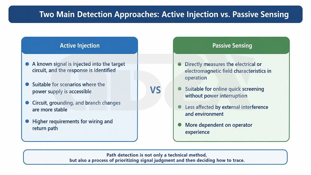
Illustration: Two main detection approaches—active signal injection and passive induction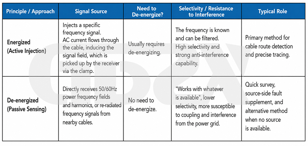
3.2 How Does the Receiver “See” the Cable Path? — Spatial Response of the Coil

Mature equipment typically provides both modes and may also offer auxiliary modes such as a broad peak and directional indication (peak plus arrow) for cross-verification. Burial depth is “calculated” rather than directly “measured”: based on the approximate inverse relationship between the magnetic field strength around a single conductor and distance, the receiver estimates the distance between itself and the cable by calculating the ratio between signals from two coils with a fixed spacing. The result is highly sensitive to signal purity, whether the cable is isolated as a single conductor, and the presence of nearby metal objects.
3.3 Typical Judgment Targets
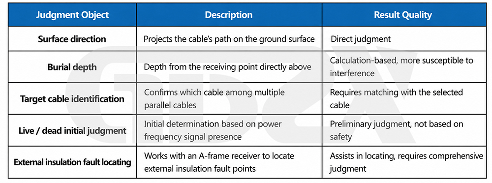
It should be emphasized that the role of cable path detection in fault work is auxiliary positioning. It brings the fault section and fault point onto ground coordinates. Final fault identification still requires comprehensive assessment using methods such as fault location and insulation testing.


