


NEWSnews
Cable Route Detection Methods, Equipment Selection & Key Parameters
4. Main Detection Methods & Applications
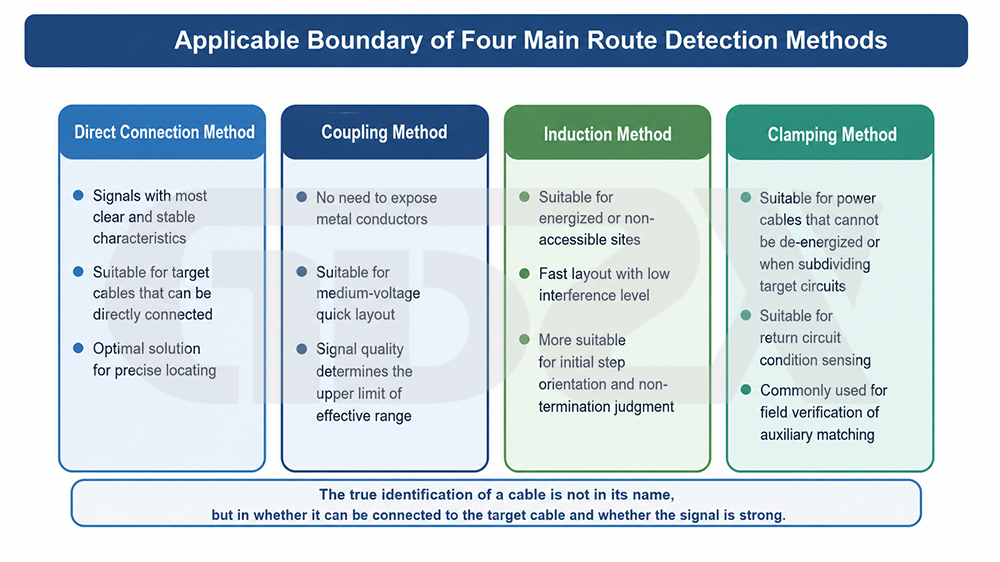
Figure: Application Boundaries of Four Main Cable Route Detection Methods
One-sentence answer: There is no single “standard procedure” in the field—use direct connection when power can be disconnected and high accuracy is required; use a signal clamp or induction when power cannot be disconnected and cable identification is required; use an A-frame for sheath fault locating; use passive detection for rapid surveys. In most cases, multiple methods are combined, progressing from coarse to fine detection.
Field detection does not rely on a single “standard procedure.” Different signal injection and reception methods should be selected according to whether the cable is energized, whether the conductor can be directly accessed, and whether the surrounding environment is complex. Understanding the applicable boundaries of these methods is more important than memorizing any particular operating procedure.
Direct connection provides the highest accuracy. The transmitter directly applies the characteristic signal to the conductor or metallic sheath of the target cable through the grounding lead and signal clamp. The signal propagates along the cable and returns through the earth or grounding at the far end. Because the signal is directly injected and its frequency is known, it provides the strongest signal, the highest selectivity, and the most reliable depth measurement. It is the preferred method for accurately determining cable routes and burial depth when both ends can be de-energized, disconnected, and connected for testing. The drawback is that power must be disconnected and connection conditions must be available.
Induction is a commonly used method for scenarios where power cannot be disconnected. The transmitter does not contact the conductor, but couples the signal to the cable through a built-in coil or clamp, without requiring disconnection or power interruption. Its limitation is that the signal may also couple to adjacent metallic utilities, resulting in reduced selectivity and a shorter effective detection distance. It is more suitable for short- and medium-distance route verification on energized or non-de-energizable cables.
The signal clamp method can be regarded as an optimized induction method. The clamp surrounds the target cable to form a magnetic coupling loop, concentrating and directing the signal into that cable. Crosstalk is significantly lower than with bare-coil induction, and selectivity is also higher. It is particularly suitable for selecting the target cable from a bundle of parallel cables in cable trenches and cable trays, and is a key method for cable identification under energized conditions.
The A-frame auxiliary method is specifically used for locating external sheath faults. A DC or pulsed signal is applied between the metallic sheath of the cable and earth. At the fault point, current flows into the ground and forms a potential gradient on the ground surface. Two probes are used to measure the ground potential difference to converge on the fault location. It does not track the cable route; it is used only to locate sheath grounding faults after the route is known, generally under de-energized conditions.
Passive detection does not inject any signal. Instead, it directly receives the 50/60Hz power-frequency magnetic field generated by the cable operating current or the re-radiation of RF signals by the cable. It requires the simplest connection and is the quickest to operate, but has the lowest selectivity. It is generally used for rapid surveys or for initially determining the approximate route when connection conditions are unavailable.
The general relationship between methods and scenarios is as follows: when power can be disconnected and accuracy is required, use direct connection; when power cannot be disconnected and identification is required, use the signal clamp or induction method; for sheath fault locating, use an A-frame; for rapid surveys without connection conditions, use passive power-frequency or RF detection. In most field applications, multiple methods are combined, progressing from coarse to fine detection and cross-verifying results using multiple criteria.
5. Equipment Classification
One-sentence answer: These devices can be classified according to four dimensions: signal source (active/passive), functional coverage (basic/comprehensive), energized-line adaptability (de-energized only/supports energized identification), and integration form (integrated portable/distributed combination). Understanding the classification is the first step in distinguishing between “sufficient” and “over-purchasing.”
Cable route detection solutions available on the market can be divided into several categories according to signal source, functional coverage, and integration form. Understanding these categories helps distinguish between “sufficient” and “over-purchasing.”
By signal source, they are classified as active and passive types. Active types incorporate a transmitter and actively inject characteristic signals, providing strong selectivity and depth-measurement capability. They are the mainstream configuration for professional operation, maintenance, and construction. Passive types have only a receiver and rely on the cable’s inherent power-frequency or harmonic signals. They are low-cost and portable, and are mainly used for basic surveys.
By functional coverage, they are classified as basic and comprehensive types. Basic cable route detection mainly addresses “route identification + depth measurement” and is suitable for applications requiring only route verification. Comprehensive types additionally integrate capabilities such as fault locating, energized identification, current measurement, and multi-frequency/multi-mode operation, covering the complete chain from route verification and fault investigation to energized cable identification.
By energized-line adaptability, they are classified into de-energized-only detection and energized identification support. De-energized-only equipment relies on direct signal injection and can only be used on cables that can be de-energized. Equipment supporting energized identification uses induction/clamp coupling for power-frequency reception, providing a wider safety boundary and suitability for critical lines that cannot be de-energized.
By integration form, they are classified as integrated portable and distributed multi-device combinations. Integrated portable equipment combines the transmitter, receiver, and accessories into one system, providing convenient transport and consistent parameter matching. It is suitable for organizations prioritizing field efficiency and having personnel with varying levels of experience. Distributed multi-device combinations consist of independent signal sources, receivers, and locating instruments. They provide greater flexibility but impose higher requirements on operators and are more suitable for organizations with dedicated laboratories and a need for maximum flexibility.
The equipment shown in the figure belongs to the type characterized by “primarily active, with passive capability, comprehensive functionality, and integrated portability.” It includes an approximately 10W transmitter for direct and induction injection, while the receiver supports multiple modes including power-frequency, RF, and passive detection. It is also equipped with accessories such as a signal clamp, A-frame, and grounding lead, covering most field requirements from route verification to fault locating and from de-energized to energized identification. This configuration represents a typical direction for current medium- to high-end field equipment, but it does not mean that all users require such comprehensive functionality.
6. Key Parameters
One-sentence answer: Parameters should not be compared by numerical magnitude alone. It is necessary to understand “why each parameter exists, what it affects, and in which scenarios it is critical”—transmitter power, frequency settings, reception modes, detection depth, current range, energized identification, display method, power supply and portability, and accessory configuration each correspond to different field trade-offs.
Equipment selection and result evaluation must ultimately return to the parameters. The key is to understand for each parameter “why it exists, what it affects, and in which scenarios it is critical.” The following provides an item-by-item explanation (see the parameter table in Section VII for specific numerical ranges).
Transmitter power determines signal loading strength and propagation distance. Higher power provides greater advantages under long-distance, deep-burial, and high-soil-resistivity conditions. However, in areas with dense cables, excessive power can instead increase crosstalk with adjacent cables. Therefore, higher power is not always better and should be balanced against typical operating distance and environmental conditions.
Transmitter frequency settings range from 128Hz to 33kHz and include multiple levels to accommodate different distances and environments. Low frequencies propagate farther and produce less crosstalk, making them suitable for long-distance tracking and areas with dense cables. High frequencies provide stronger coupling and higher sensitivity, making them suitable for close-range detailed detection or situations where direct connection is difficult (see Section X for details).
The receiving frequency bands and operating modes determine which signal sources the equipment can process. Supporting both active reception and passive reception of power-frequency and RF signals means that the equipment can handle various conditions, including de-energized, energized, and loaded or unloaded cables. When full-condition coverage is required, switchable multi-mode operation is necessary.
Detection depth is the upper limit of burial depth under the specified ideal conditions. The actual achievable depth in the field is constrained by soil conditions, adjacent metal, and signal strength, and is often lower than the specified value. When evaluating this parameter, the premise of a “no-interference condition” must be kept in mind; actual performance shall be based on field measurements.
The current measurement range determines whether load current can be read on energized cables, assisting in identifying the target cable and determining its energized status. The range should cover the commonly encountered load range of the organization so that multiple energized cables can be distinguished based on their current characteristics.
Energized identification capability directly determines whether operations can be performed without power interruption. It is related to whether the equipment is suitable for critical lines that cannot be de-energized and to the safety margin of the operation. For energized operations, it is almost a prerequisite for equipment access.
The display method affects reading efficiency and record retention. Compared with purely audible indication, digital display provides quantitative readings that can be recorded and verified, reducing reliance on operator experience. This is particularly important for organizations with personnel turnover, record-retention requirements, and new personnel training.
The power supply method and portability determine field operating endurance and carrying burden, directly affecting continuous operating time and fatigue during route inspection. During long-distance continuous outdoor operations, operating endurance, charging method, and overall equipment weight should all receive particular attention.
Accessory configuration determines whether the functional scope can be expanded. The availability of an A-frame determines whether sheath fault locating can be performed, while the availability of a signal clamp determines whether energized cable identification can be performed. Where fault locating or energized cable identification is required, the corresponding accessories must be fully configured.


