


NEWSnews
Distribution Transformer Winding Material Testing: Parameters, Wiring & Analys
七、Distribution Transformer Winding Material Testing Equipment: Parameter Table and Typical Specifications Explanation
How should the parameters be interpreted? It is not simply about whether the numbers are higher or lower, but what they mean for the identification results and on-site application.
The table below shows typical configuration parameters and may be cited separately. The values in the table are examples; refer to the product technical documentation for specific parameters.
Parameter Name | Typical Range or Example Parameters | Parameter Description | Impact on Test Results | Key Selection Considerations |
Power Supply | Three-phase 380 V ±10%, 50 Hz | Operating Power Supply for the Main Unit and Excitation Unit | Voltage fluctuations beyond the specified limit may affect excitation stability and identification consistency. | Whether the ±10% Tolerance Is Sufficient for Actual On-Site Grid Voltage Fluctuations |
Operating Temperature | -10℃~50℃ | Normal Operating Ambient Temperature Range | Exceeding the specified range may cause drift and affect the accuracy of temperature correction. | Whether It Covers Local Extreme Climate Conditions
|
Operating Humidity | 5%~90%RH(25℃) | Permissible Relative Humidity for Normal Operation | High humidity may cause insulation and terminals to become damp, increasing the risk of misjudgment. | Particular attention should be paid to the upper limit in hot and humid southern regions. |
Operating Altitude | ≤2000m | Maximum Rated Operating Altitude | High altitude affects insulation and heat dissipation. | High-Altitude Areas Require Specific Confirmation. |
Display Method | Touchscreen, displaying parameters/waveforms/results | Human-Machine Interaction and Result Presentation | Without waveform data, it is difficult to verify borderline cases. | Whether Waveforms and Trends Are Displayed Rather Than Only the Results |
Temperature Measurement | On-site temperature measurement for correction. | Ambient or Winding Temperature Measurement | Failure to apply temperature correction may result in systematic misjudgment. | Whether Temperature Correction Logic Is Built In |
Detection Method | Non-Contact Excitation + Terminal Electrical Parameter Acquisition
| Core Detection Method | The more limited the detection method, the weaker its ability to detect concealed or misleading material characteristics. | Whether Multi-Parameter Comprehensive Identification Is Used |
Identification Output | Copper/Aluminum Material Tendency + Supporting Parameters | Result Format | Providing only the conclusion without supporting evidence makes the result difficult to trace. | Whether Reports and Raw Data Can Be Exported |
Operating System | Industrial-Grade Operating System | Software Platform | Affects On-Site Stability | Resistance to On-Site Electromagnetic and Temperature Interference |
How to Read the Parameter Table: The Rows Closer to “Method” and “Identification Criteria” Determine the Accuracy of the Measurement, While the Rows Closer to “Environmental Conditions” Determine Whether the Device Is Suitable for Use in Your Site.
八、Test Wiring, Detection Circuit, and On-Site Operating Logic
How should the device be connected on site? First confirm the prerequisites, then clarify the excitation circuit and measurement circuit, and finally connect them in sequence.
Even without a diagram, readers can be guided through the on-site procedure step by step.
8.1 What Components Make Up the Detection Circuit?
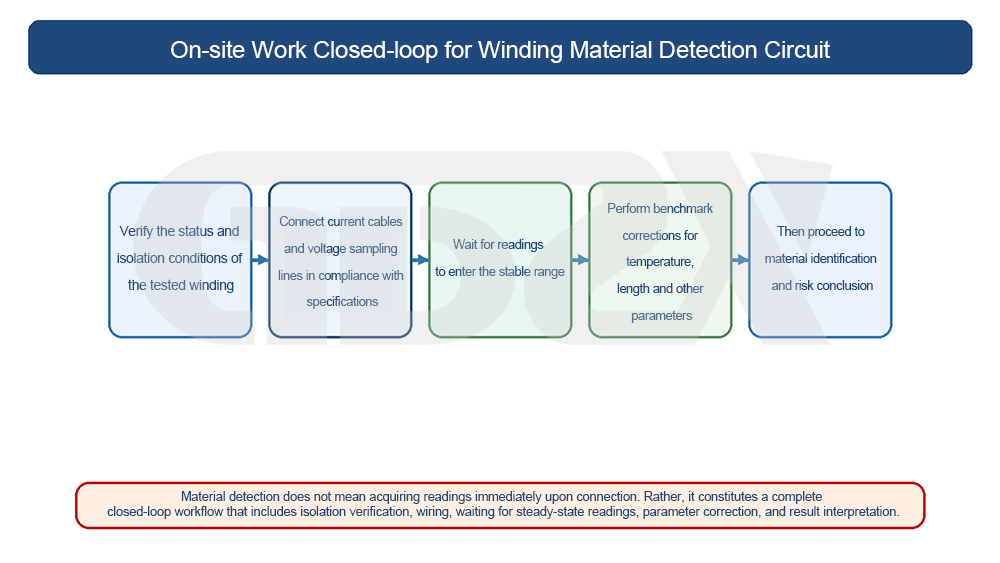
Figure: On-Site Closed-Loop Operation of the Winding Material Detection Circuit
A complete detection circuit typically includes a portable main unit (excitation and computation), a detection unit or probe (connection/coupling with the winding terminals), the transformer winding under test, a temperature probe, and reliable grounding and power connections.
The non-contact excitation section injects an excitation signal into the winding or conductor; the terminal conductive-parameter acquisition section measures electrical parameters such as winding resistance and conductive response. The former “provides the signal,” while the latter “reads the response.” Only when the two work together can a basis for material identification be established.
8.2 Prerequisites That Must Be Confirmed Before Testing
1. The transformer has been reliably de-energized, discharged, and grounded in accordance with applicable procedures.
2. Record the nameplate information, including capacity, voltage level, connection group, nominal winding material, and rated current.
3. Confirm and record the tap changer position. When comparing multiple units, the tap positions should be consistent.
4. Record the ambient temperature and humidity to provide data for temperature correction.
5. Check the cleanliness of the terminals and remove oxidation and oil contamination.
8.3 On-Site Testing Sequence
1. De-energize, verify the absence of voltage, ground, and discharge.
2. Record the nameplate information and tap position.
3. Connect the detection unit to the winding terminals, ensuring reliable contact.
4. Position the temperature probe and record the environmental parameters.
5. Start excitation and data acquisition, then read the parameters and waveforms.
6. Repeat the measurement several times on the same phase and, when necessary, compare the three phases.
7. Perform a comprehensive identification based on the capacity and conductor cross-sectional-area logic, then generate the report.
8.4 What Misjudgments Are Most Likely to Result from Improper Wiring?
1.Poor contact or oxidized terminals: excessive contact resistance may cause copper to be misidentified as aluminum.
2.Temperature not corrected: higher resistance at elevated temperatures may result in systematic misjudgment.
3.Inconsistent tap positions: different numbers of turns make the parameters incomparable during three-phase or multi-unit comparisons.
4.External electromagnetic interference: coupling from nearby energized equipment may distort the waveform.
5.Surface coating not removed: non-contact coupling may be obstructed, resulting in a weak excitation signal.
In one sentence: Most on-site misjudgments in material identification are not caused by inaccurate equipment, but by improper wiring and failure to meet the necessary prerequisites.
九、Common Calculation Formulas, Temperature Correction, and Result Interpretation Logic
What is the underlying logic for identifying the winding material? It is to cross-verify resistance, resistivity, temperature, and cross-sectional area within the same set of formulas, rather than relying on a single formula.
9.1 Basic Resistance Formula
Conductor resistance:
R = ρ · L / S
where R is resistance (Ω), ρ is resistivity (Ω·mm²/m), L is conductor length (m), and S is conductor cross-sectional area (mm²).
9.2 Resistivity Conversion
Rearranging the above formula gives:
ρ = R · S / L
When the winding geometry parameters are known, the equivalent resistivity can be calculated and compared with the standard resistivity values of copper and aluminum as one of the criteria for material identification.
9.3 Temperature Correction
The resistance of metals increases as temperature rises. In engineering practice, the measured resistance is often converted to the standard reference temperature of 20°C for comparison:
R₂₀ = Rt · (1 + α·(20 − t))⁻¹ (approximate conversion, where t is the measured temperature and α is the temperature coefficient of resistance)
The α value is approximately 0.00393/°C for copper and 0.00403/°C for aluminum. Without temperature correction, measured resistance will be systematically higher in summer and lower in winter, directly affecting copper-versus-aluminum identification.
9.4 Identification Significance of the Resistivity Difference Between Copper and Aluminum
The resistivity of copper is approximately 0.0172 Ω·mm²/m and that of aluminum is approximately 0.0283 Ω·mm²/m at 20°C. Aluminum is approximately 1.6 times more resistive than copper. After conversion to 20°C, if the equivalent resistivity falls within the aluminum range while the nameplate specifies all-copper windings, the result should be considered potentially inconsistent. Copper-clad aluminum falls between the two and therefore requires particular attention.
9.5 Cross-Sectional Area Logic for the Same Conductive Target
To achieve the same resistance (conductivity), according to S = ρ·L/R, aluminum requires a larger cross-sectional area S because its resistivity ρ is higher. This is the engineering basis for the fact that “aluminum windings generally have a larger cross-sectional area than copper windings.” Material identification must therefore be combined with the capacity rating and nominal cross-sectional area; otherwise, “large-cross-section aluminum” may be mistaken for “small-cross-section copper.”
9.6 Why Material Differences Affect Losses and Heating
Winding loss:
P = I² · R
If the material is inconsistent with the specified material and causes R to be higher, then under the same load current I, power loss P and heat generation will increase accordingly. This is the physical reason why a material mismatch ultimately manifests as excessive temperature rise.
9.7 Core Principles for Result Interpretation
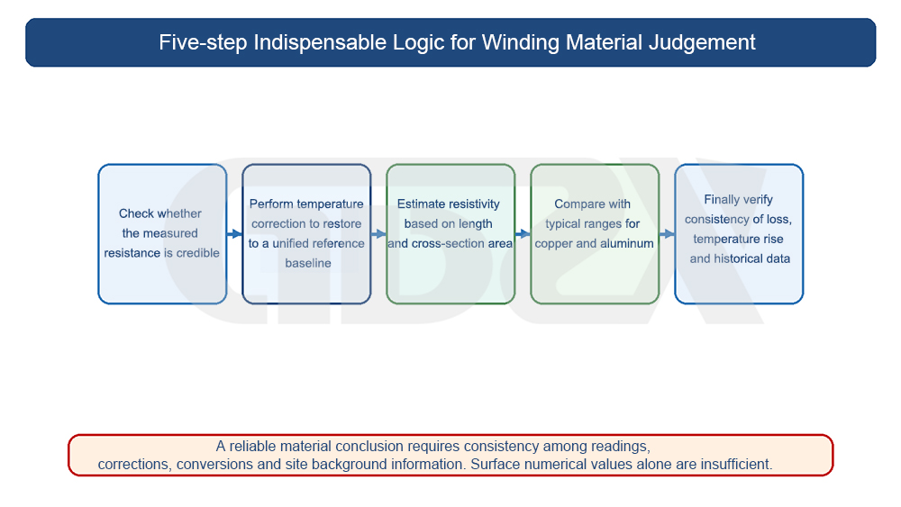
Figure: The Five-Step Logic That Must Not Be Omitted in Winding Material Identification
Material identification cannot be determined by mechanically applying formulas. It must be assessed comprehensively based on the capacity rating, winding structure, conductor cross-sectional area, measured temperature, manufacturing process background, waveform characteristics, and results from repeated measurements. Any single resistance value is insufficient to establish a definitive conclusion, especially in boundary cases such as copper-clad aluminum.


