


NEWSnews
Capacitive Current Testers: Scope, Methods, Selection, FAQs & Value
十、What Problems Can It Solve, and What Devices or Tests Can It Not Replace?
What Are Its Boundaries? It Provides Measured Capacitive Current Data but Cannot Replace Arc Suppression Coil Tuning, Faulty Line Selection, Insulation Monitoring, or Offline System Calculations
To accurately define the role of this type of equipment, it is important to clarify both what it can do and what it cannot do. This is particularly important for equipment procurement and field applications.
The core problem it solves is providing measured capacitive current to ground and system-to-ground capacitance data for the distribution network. These measured parameters can serve as a basis for neutral-point grounding mode calculations, arc suppression coil selection and tuning verification, single-phase grounding fault analysis, faulty line selection, and protection setting coordination. Its key value lies in actual measurement—using real field data instead of drawing-based estimates or outdated records.
However, it has clear functional boundaries and cannot replace the following types of equipment or work:
It is not an arc suppression coil tuning or control device. The tester is responsible for determining “how much the capacitive current is,” while an automatic arc suppression coil tuning device is responsible for “continuously adjusting the compensation tap and tracking the detuning level in response to system changes.” The former is an intermittent measurement tool, while the latter is an online control device for continuous operation. One provides verification data, while the other performs continuous compensation. They cannot replace each other.
It is not a ground-fault line-selection device. A line-selection device is designed to quickly determine “which feeder has the single-phase ground fault” when a fault occurs, supporting fault handling. The tester, by contrast, measures the overall system capacitive current during normal operation. Their objectives are fundamentally different. The measured capacitive current from the tester can provide a reference for line-selection device settings, but the tester does not perform real-time faulty line selection.
It is not an insulation monitoring device. Online insulation monitoring focuses on continuously monitoring insulation condition and detecting insulation defects, whereas the tester focuses specifically on the parameter of capacitive current to ground. Their monitoring objectives are different.
It also cannot completely replace offline tests or system modeling and calculations. Offline tests, parameter modeling, and scheme verification each have their own purposes. The tester provides key input data rather than the complete conclusion. Scheme verification still requires incorporating the measured data into a system model for comprehensive analysis.
In short: the tester is the “provider of measured field data,” the arc suppression coil tuning device is the “executor of continuous compensation,” the line-selection device is the “judge for fault location,” and the insulation monitoring system is the “monitor of insulation condition.” Each serves a distinct role in the grounding system. The tester fills the “field measurement” gap, but it cannot replace the others.
十一、Comparison of Similar Methods: Why This Type of Equipment Is Suitable for On-Site Distribution Network Measurement
How to Choose Among the Four Methods? See the Table Below—The Open-Delta Heterodyne Method Stands Out for No Outage, Safety, and Repeatable Measurements.
The various methods discussed above are compared side by side in the table below, allowing readers to quickly understand their differences and select the most suitable method.
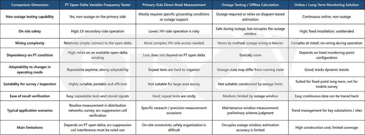
As shown in the table, the key reason why the PT open-delta heterodyne method is well suited for on-site measurement in distribution networks is that it combines safety, no outage, simplified wiring, and repeatable measurements—features that closely match the characteristics of distribution network sites, where there are many locations, conditions change rapidly, and routine surveys are often required.
Its main limitations are that it depends on the availability of a PT open-delta connection and requires the influence of the arc suppression coil to be properly accounted for. Understanding these limitations helps users select the right method for the right application: it is particularly convenient for routine surveys and arc suppression coil verification, while special high-accuracy measurements or long-term trend monitoring may require it to be combined with other methods.
十二、How to Select a Distribution Network Capacitive Current Tester: A Procurement Perspective
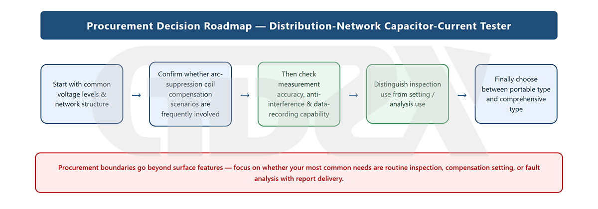
Illustration: Key Procurement Criteria for Selecting a Distribution Network Capacitive Current Tester
What is the biggest mistake to avoid when purchasing? Looking only at price and measurement range. What truly determines whether the equipment performs well in the field is its connection compatibility, interference resistance, verification capabilities, and reporting functions.
When purchasing this type of equipment, the biggest mistake is to focus only on price and the nominal measurement range. Differences in price often reflect less visible capabilities, such as anti-interference algorithms, PT compatibility, historical data management, report generation, field adaptability, and after-sales training.
Different organizations have different application scenarios, so their configuration requirements also vary. The table below provides practical recommendations for equipment selection.
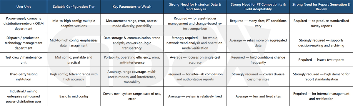
When selecting a tester, keep the following principles in mind:
1. Match the measurement range and accuracy to the actual capacitive current level of the system. For urban distribution networks with a high proportion of cable lines and relatively large capacitive currents, prioritize instruments with wider measurement ranges and high accuracy across multiple ranges.
2. Ensure the connection method is compatible with the on-site PT and neutral-point conditions. For sites with diverse configurations, choose a model offering multiple connection and compatibility options.
3. Anti-interference performance is a critical requirement in environments with significant harmonics and frequent switching operations. This should not be compromised.
4. Historical data management and report export are essential for organizations that require equipment records, trend analysis, and formal reports. For smaller users with stable and fixed system conditions, these requirements can be relaxed appropriately.
5. Do not overlook training and after-sales support. The reliability of measurement results depends approximately half on the equipment and half on the operator. PT compatibility consultation, on-site training, and long-term technical support are often what ultimately determine the actual effectiveness of the equipment.
十三、Frequently Asked Questions (FAQ)
Basic Understanding
Q1: What exactly does distribution network capacitive current mean?
It refers to the current flowing through the distributed capacitance between each phase and ground during normal operation or a single-phase ground fault. In engineering practice, the primary concern is the sum of the three-phase capacitive currents to ground during a single-phase ground fault, which reflects the overall level of system-to-ground capacitance.
Q2: Why is this value particularly important in small-current grounding systems?
Because in small-current grounding systems, the single-phase ground-fault current is mainly capacitive current. It determines whether the grounding arc can extinguish naturally, whether an arc suppression coil is required, and the level of overvoltage risk. It is therefore a core parameter of such systems.
Q3: Is a high capacitive current good or bad?
There is no absolute good or bad. The key is whether it is properly matched to the grounding method and compensation scheme. A relatively high capacitive current without compensation or with improper compensation can make arc extinction difficult and increase the risk of overvoltage. With appropriate arc suppression coil compensation, systems with relatively high capacitive current can also operate safely.
Q4: Why can't drawing-based calculations replace actual measurements?
Because estimates rely on records such as line length, conductor type, and cable ratio. After network expansion, modification, or changes in operating configuration, the actual network often differs from the records. Estimates can only provide an approximate reference, while accurate data must come from on-site measurements.
Methods and Result Interpretation
Q5: Why use a heterodyne signal instead of the power-frequency signal?
The system itself contains power-frequency voltage, current, and harmonics. If the test signal also uses the power frequency, it is difficult to distinguish it from these disturbances. By using a signal at a frequency different from the power frequency, the instrument can use frequency-selective detection to extract only the response to its injected signal, providing better interference resistance and measurement accuracy.
Q6: How can measuring on the low-voltage secondary side reflect the primary-side capacitance?
The PT maps the primary system's voltage to the secondary side according to its transformation ratio. Any system-to-ground capacitance imbalance leaves measurable electrical characteristics in the open-delta winding. By injecting a heterodyne signal on the secondary side, measuring the response, and converting the result according to the PT ratio, the primary-side system-to-ground capacitance can be derived.
Q7: Are the measurements reliable when the arc suppression coil is in service?
Extra caution is required. When the arc suppression coil is in service, it compensates for part of the capacitive current. The directly measured value may therefore represent the compensated current rather than the system's inherent capacitive current. Its influence should be handled or excluded according to the instrument's specified method; otherwise, misjudgment may occur.
Q8: Why is one measurement not enough? Why should the measurement be repeated?
A single reading is only a snapshot of a particular operating condition at a particular moment. Repeated measurements can verify consistency. Only by combining repeated results with historical data and system configuration can the reliability of the measurement be assessed. If the result differs significantly from historical values, first check the operating configuration and wiring parameters rather than accepting the reading immediately.
Application and Scenario
Q9: When should the capacitive current be measured again?
Re-measurement should be performed after line expansion, replacement of overhead lines with cables, network configuration changes, arc suppression coil modifications, changes in the grounding method, or significant changes in the operating configuration. If system parameters change without re-measurement, compensation and protection settings may become inaccurate.
Q10: Can this type of instrument be used at substations without an open-delta winding?
PT open-delta connection-based instruments require an available open-delta winding. If the site does not have one, a neutral-point connection type or another compatible version should be used. The on-site PT configuration must be verified before equipment selection.
Q11: Will the test affect normal system operation?
This type of method operates on the low-voltage secondary side, while the primary system remains energized. It injects a small heterodyne excitation signal and normally does not affect normal system operation. However, standardized procedures must still be followed, and the safety of the secondary circuit must be confirmed to prevent accidental contact or incorrect connections.
Q12: Will heavy harmonics at the site affect measurement accuracy?
Harmonics can introduce interference, but heterodyne frequency-selective algorithms are specifically designed to address such interference. Instruments with strong anti-interference capabilities can maintain good accuracy even in high-harmonic environments. This is therefore an important specification to evaluate when selecting equipment for complex sites.
Procurement and Selection
Q13: Why shouldn't procurement decisions be based on price alone?
Because price differences often reflect differences in less visible capabilities, such as anti-interference algorithms, PT compatibility, historical data management, report generation, and after-sales training. Lower-cost instruments may experience reduced accuracy or limited compatibility under complex operating conditions, resulting in higher overall costs of use.
Q14: How should the procurement boundaries between open-delta method instruments and other measurement methods be defined?
For routine surveys without outages and arc suppression coil verification, the open-delta heterodyne method should be prioritized. For long-term trend management, online monitoring is more appropriate. For precise measurements during specific maintenance outages, offline methods can be used. For most distribution network utilities, the open-delta method can serve as the primary approach, with other methods used as supplementary means.
Q15: Which organizations should choose high-configuration models, and which can use basic models?
Power utility operation and maintenance departments, dispatching and technical departments, and third-party testing organizations typically deal with numerous sites, diverse conditions, and high reporting requirements. They are better suited to medium- or high-configuration models with broader compatibility. Industrial and mining users with relatively fixed systems and a small number of sites can generally meet their needs with basic to medium configurations.
Q16: Which hidden capabilities are most likely to be overlooked during procurement?
The most commonly overlooked capabilities include anti-interference performance, PT compatibility, historical data and trend management, standardized report export, and on-site training and after-sales support. These capabilities may not appear prominently in the headline specifications, but they directly affect actual usability and data reliability.
Q17: Why can prices differ significantly between instruments? Where do the main differences lie?
The main differences lie in measurement accuracy and range-specific error, measurement range coverage, connection flexibility, maturity of anti-interference algorithms, data management and reporting capabilities, and the manufacturer's technical support and after-sales service. Instruments that provide both strong core specifications and comprehensive supporting capabilities naturally tend to have higher costs.
Q18: What should third-party testing organizations pay particular attention to when selecting equipment?
The equipment should provide clear and traceable evaluation criteria, exportable raw data and measurement results, and standardized report formats. Because third-party organizations issue reports externally, the data must withstand verification and technical scrutiny. Wide compatibility, high accuracy, and multiple connection methods are therefore particularly important.
十四、Conclusion: What Is the True Engineering Value of This Type of Equipment?
Its value does not lie in replacing any particular device or test, but in providing the entire grounding system analysis with a real and verifiable source of measurement data.
Let us return to the feeder at the beginning, where the grounding arc failed to extinguish promptly. The problem was not necessarily a malfunction of the arc suppression coil. Rather, the system's capacitive current to ground had already changed as the network expanded, yet no one had carried out timely measurement and verification. The true value of a distribution network capacitive current tester lies in answering the fundamental question—“What is the system's actual capacitive current right now?”—through an efficient on-site method that can be performed without an outage and from the low-voltage side.
It is not the most prominent device in the grounding system, nor does it perform real-time control or fault location. However, the measured data it provides serves as the common starting point for **neutral-point grounding mode calculations, arc suppression coil selection and tuning, fault analysis, and protection setting coordination**. When the source data is accurate, subsequent compensation, protection settings, and operating-mode optimization have a reliable basis. If the source data is inaccurate, even the most sophisticated tuning device is still operating against an incorrect reference.
Taking the type of test instrument shown in the figure, which uses the PT secondary-side open-delta heterodyne method** as an example, its engineering significance can be summarized in three points:
1. Replacing estimation with measurement: Grounding system analysis can be based on actual field data rather than theoretical estimates.
2. Making routine surveys and post-change re-measurements practical: Measurements can be performed without an outage and from the low-voltage side, improving field efficiency and safety.
3. Making capacitive current a manageable and traceable parameter: Through standardized measurement, verification, and reporting, capacitive current becomes a basic parameter that can be systematically managed and tracked rather than a figure checked only occasionally.
For purchasers, the key to selecting the right equipment is to move beyond the conventional approach of simply comparing prices and nominal measurement ranges. Instead, evaluate whether the instrument matches the grounding method and capacitive current level of the actual system, whether it is compatible with on-site PT conditions, whether its anti-interference performance is reliable, and whether its data management and reporting capabilities meet operational requirements.
When properly selected, this type of instrument may not be the most conspicuous part of the distribution network grounding system, but it serves as an unobtrusive yet indispensable starting point in the safety management chain.
This article is compiled based on publicly available standards, specifications, and general engineering application information in force as of August 2026. Actual testing and equipment selection should be based on the currently effective national and industry standards, applicable technical documentation, and the specific operating conditions of the site.


