


NEWSnews
Handheld Transformer Ratio Tester: Principles, Importance, Criteria & Methods
一、What Is a Handheld Transformer Turns Ratio Tester?
One-sentence answer: It is a portable, dedicated instrument designed to quickly measure a transformer’s voltage ratio on site without disassembly, while also assisting in identifying the vector group designation and tap position.
Let’s start with a real-world scenario. A 10 kV distribution transformer has just been lifted into position, and the installation team is preparing to perform commissioning and acceptance tests. There is no stable external power supply on site, and connecting phase by phase is time-consuming. The team leader takes out a palm-sized instrument and connects it to the bushing terminals. Within seconds, the screen displays the three-phase turns ratio and vector group. The results match the nameplate, and when the tap is switched, the ratio changes step by step in a consistent pattern. The transformer can then move forward to the next stage of the commissioning process.
A handheld transformer turns ratio tester is designed to address this type of field requirement—mobility, de-energized testing, and time-sensitive work. It integrates the test power source, measurement circuitry, identification algorithms, and touchscreen into a compact body that can be operated with one hand. Its built-in battery allows testing without relying on the site’s mains power supply.
Its function is straightforward: apply a known test voltage to the winding, measure the corresponding induced voltage on the other side, calculate the measured turns ratio, and compare it with the rated ratio on the nameplate to determine the deviation. At the same time, it identifies the vector group designation based on the phase relationship and amplitude, and works with the tap changer to verify the variation in ratio at each tap position. It does not measure insulation, temperature rise, or mechanical deformation. It answers one seemingly simple but critically important question: Are the transformer’s turns ratio and connection configuration correct and stable?
One common misunderstanding should be clarified: its role is screening and verification, rather than comprehensive diagnosis. It provides the turns ratio, vector group, and tap-position verification results and supporting parameters, helping determine whether the transformer is suitable for commissioning or requires further investigation. It is not a substitute for the complete transformer testing system.
二、Why Is Turns Ratio Testing So Important in Transformer Testing?
Why Is Turns Ratio Testing So Important in Transformer Testing?
Why specifically test the turns ratio? Because it is a basic verification that is applicable throughout the transformer life cycle, costs very little, and covers a wide range of potential issues. With minimal effort, it helps ensure that the transformer’s electrical identity is correct and its winding relationships remain sound.
The turns ratio is one of the transformer’s most fundamental electrical characteristics. From factory production to site commissioning and long-term operation and maintenance, it is used at every key stage as a means of verification. Factory testing verifies whether the winding ratio, tap design, and vector group conform to the design. Acceptance testing after delivery and installation rechecks the ratio and vector group to confirm that transportation or installation has not introduced errors and that the delivered transformer is indeed the one specified in the order. Tests during initial commissioning and preventive maintenance help identify changes in the winding or tap changer condition through repeated measurements. After maintenance or overhaul, retesting provides a direct way to verify that the transformer is still correctly assembled.
According to GB 50150, DL/T 596, and the GB 1094 series, inspections of the voltage ratio and vector group designation are explicitly specified test items. In other words, whether to perform a turns ratio test is not simply a matter of preference; it is a required test item under the applicable standards and procedures.
The time and equipment costs of a turns ratio test are negligible compared with the risks it can prevent. Incorrect vector group connections during parallel operation can cause circulating currents, severe electrical transients, and even equipment damage. A mismatch between the actual tap position and the assumed voltage-regulation setting can result in prolonged operation away from the rated voltage. Early signs of interturn short circuits, if not detected before commissioning, may develop into serious faults. A turns ratio test that takes only a few minutes therefore acts as a low-cost barrier against potentially high-consequence failures.
Example: Before two distribution transformers were operated in parallel in one area, the maintenance team used the same handheld tester to verify both units. The turns ratio values themselves appeared normal, but comparison of the vector groups revealed the problem immediately: one transformer was Yyn0, while the other had been connected on site as Dyn11. Without this field verification, closing the parallel connection could have had serious consequences.
The conclusion is clear: the value of turns ratio testing is not simply in how many major faults it detects, but in its ability to provide a low-cost, high-frequency safeguard for the quality and operational safety of large numbers of transformers.
三、Engineering Background of Turns Ratio, Vector Group, Tap Position, and Field Fault Clues
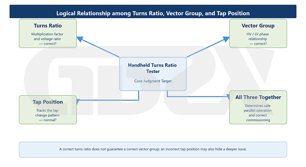
Illustration: Logical Relationship Among Turns Ratio, Vector Group, and Tap Position
Engineering Background of Turns Ratio, Vector Group, Tap Position, and Field Fault Clues
What is the difference between turns ratio, vector group, and tap position? Ultimately, they are reflected in four key observations: measured ratio, phase relationship, three-phase consistency, and tap-change pattern. Understanding turns ratio testing means learning to interpret these four dimensions together.
The turns ratio is an amplitude ratio that answers, “Is the voltage transformation ratio correct?” The vector group designation describes the phase relationship between the high- and low-voltage side line voltages and answers, “Is the phase identity correct?” The tap position determines the adjustable transformation ratio, with each tap corresponding to a specific designed ratio. These three types of information are independent, yet they must be evaluated together.
3.1 Turns Ratio Abnormality and Wiring Errors: Separate Values from Relationships
When the measured turns ratio of one phase deviates significantly from the rated value, the first questions should be whether the wiring is incorrect, the wrong tap position has been selected, or the winding itself has a problem. A proportional deviation across all phases is often related to the tap position or wiring, whereas an abrupt deviation in only one phase is more likely to point to that phase’s winding or lead. However, when the high- and low-voltage terminals are mismatched or the phase sequence is reversed, an individual ratio may still appear to fall within a reasonable range. The problem may instead be revealed by the relationships among the three phases. This is precisely why the test cannot focus on a single value and must consider all three phases together.
3.2 Vector Group Error: Correct Turns Ratio but Wrong Vector Group Is Still a Major Problem
Two transformers may have exactly the same turns ratio but different vector groups. If operated in parallel, they can produce circulating currents. The vector group identification function of a turns ratio tester is designed to verify this additional layer of phase identity beyond numerical ratio measurements. This is exactly the type of problem that can be prevented through parallel-operation verification.
3.3 Abnormal Tap Position: The Pattern Matters More Than the Individual Value
Whenever the tap changer moves by one step, the turns ratio should change in a regular stepwise pattern, with each tap corresponding to a designed ratio increment. If one tap produces an irregular jump, or if repeated measurements at the same tap are unstable, this strongly suggests a problem even when the absolute value does not appear significant. Possible causes include poor contact at the tap-changer contacts, problems with the tap leads, or a mismatch between the actual tap position and the displayed position.
3.4 Early Signs of Interturn Faults and Parallel Consistency: Subtle but Detectable
Early deterioration of interturn insulation may cause a small change in the effective number of turns in a phase, appearing as a slight deviation in the turns ratio or increased three-phase imbalance. A single measurement at a single point may not reveal the issue. However, when combined with historical trends, three-phase comparison, and measurement repeatability, turns ratio testing can provide valuable early warning clues. For transformers operating in parallel, the turns ratio, vector group, and impedance voltage must also be consistent. This makes pre-energization consistency verification one of the key applications of a turns ratio tester.
Example: After a main transformer underwent core inspection and maintenance, it was reassembled and retested. The overall turns ratio deviations were within the allowable range, but at one tap position on phase C, the measured ratio suddenly shifted and remained unstable over three repeated measurements. Following this clue that the expected pattern had been broken, the investigation eventually identified poor contact at a moving contact of the tap changer.
The conclusion is straightforward: these seemingly separate problems are actually reflected through four common observation dimensions—ratio, phase relationship, three-phase consistency, and tap-change pattern. Understanding this allows you to move beyond simply reading one number and instead interpret four dimensions simultaneously.
四、Which Applications Are Best Suited to the Main Transformer Turns Ratio Testing Methods?
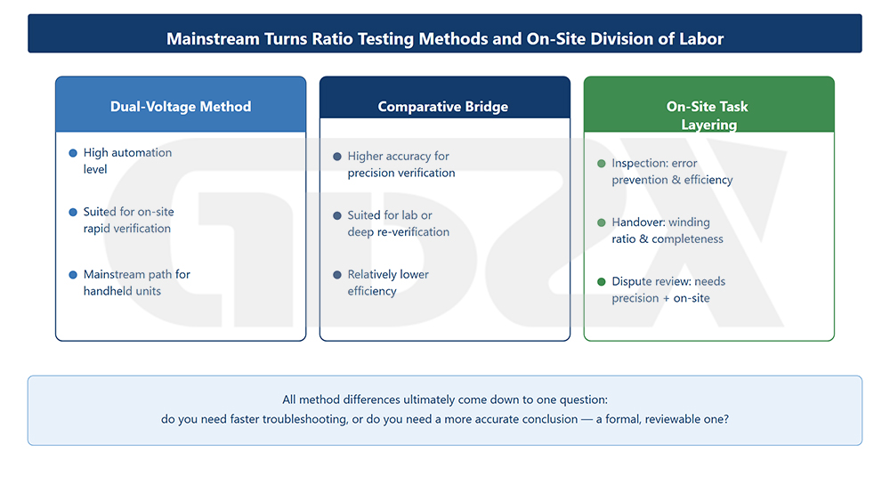
Illustration: Main Transformer Turns Ratio Testing Methods and Their Field Applications
What are the main ways to measure transformer turns ratio? The single-phase method, three-phase method, vector group identification, and tap-by-tap verification each serve a different purpose. In modern field applications, the mainstream approach is a combination of three-phase simultaneous testing + vector group identification + tap verification.
The first is the single-phase method: voltage is applied and measurements are taken phase by phase on a three-phase transformer, followed by manual comparison and analysis. The principle is straightforward and the equipment requirements are relatively low, so it is still used for detailed verification and with older equipment. Its disadvantages are lower efficiency, more frequent reconnections, and a relatively higher risk of human error.
The second is the three-phase method (simultaneous three-phase testing): with a single connection, the instrument automatically applies test voltage and performs measurements on all three phases, directly providing the three-phase turns ratios, vector group, and degree of imbalance. It offers high efficiency and reduces the risk of wiring errors. This is the mainstream approach for modern equipment, including handheld testers, and is especially suitable for rapid, repetitive field verification.
The third is automatic vector group identification: while measuring the turns ratio, the instrument automatically determines the vector group designation based on the amplitude and phase relationships of each phase, commonly covering groups 1–11. This allows the numerical ratio and phase identity to be verified in a single test, making it particularly useful for parallel-operation checks and acceptance testing.
The fourth is tap-by-tap verification: the transformer is tested at each tap position in conjunction with an on-load or off-circuit tap changer, while observing the stepwise pattern of the turns ratio. This is not an independent “method” in itself, but rather an extension of turns ratio testing into the tap-position dimension. It is an important part of evaluating the condition of the voltage-regulation system.
In engineering practice, the appropriate approach should be selected according to the application. Laboratory or factory precision verification generally favors equipment capable of both single-phase and three-phase testing with high accuracy. Acceptance testing and initial commissioning favor rapid conclusions through a combination of three-phase simultaneous testing, vector group identification, and tap verification. Field inspections, mobile operations, and short outage windows favor portable, battery-powered handheld instruments. Pre-parallel consistency checks favor equipment that can quickly compare the turns ratios and vector groups of multiple transformers.
There is no absolute best method. The key is matching the testing method to the application scenario.


