


NEWSnews
Handheld Transformer Turns Ratio Testers: Overview & Field Use
五、What Types Are Available and How Do They Differ?
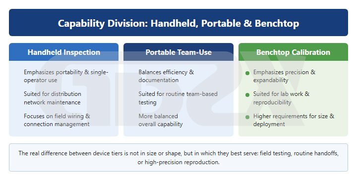
Figure: Functional division of handheld, portable, and benchtop equipment
Why do devices differ so much in form even though they all measure the transformer turns ratio? The difference lies in the trade-off between portability, accuracy, and testing depth—mobility and laboratory-level accuracy are often difficult to achieve at the same time.
By form factor, these devices can be classified into handheld units (mainly for on-site screening and verification), conventional benchtop units (mainly for in-depth verification in laboratories or fixed workstations), three-phase fully automatic units (the primary choice for many field maintenance teams), and turns-ratio modules integrated into transformer comprehensive test systems (one function of a multifunctional platform).
Handheld units excel in mobility and field adaptability. They are ideal for a “technician follows the transformer” mode of operation. Their limitation is that their ultimate measurement accuracy and complex data post-processing capabilities are generally inferior to those of benchtop units and comprehensive test platforms. Benchtop units are designed for detailed verification in laboratories and fixed workstations, offering high accuracy and stability but limited mobility. Three-phase fully automatic units strike a balance between efficiency and accuracy and are widely used as the primary field-testing equipment by many maintenance teams. The trade-off is that they are larger and heavier than handheld units. The turns-ratio module in a comprehensive transformer test system can be described as “also capable of measuring turns ratio.” Its real value lies in integrating turns-ratio testing with DC resistance, loss, and other tests for in-depth diagnosis. Using such a system solely for turns-ratio measurement would be an overuse of its capabilities.
A common misjudgment occurs when a simple device that can only perform phase-by-phase measurement and lacks vector group identification is used for parallel-operation verification. It may verify only the numerical ratio while overlooking the vector group, allowing wiring or vector group errors to go undetected. Such boundary cases require the combined capability of three-phase simultaneous measurement and vector group identification.
The key to equipment selection is not simply “Can it measure the turns ratio?” but rather “Can it measure the turns ratio quickly and accurately under the field conditions you encounter most often?” The comparison table in the next section will compare these four types of equipment side by side.
六、How to Assess Key Components and Parameters Using the Device Shown in the Figure
What Should You Look at First When Evaluating a Handheld Transformer Turns Ratio Tester? Focus on its structural design, power supply and environmental adaptability, identification and display capabilities—not on any single impressive specification.
Using a typical handheld transformer turns ratio tester as an example (the following specifications are typical/example configurations and should be verified against the actual technical documentation), this is a typical all-in-one handheld unit. It features touchscreen operation, with the battery, test power supply, and measurement circuits integrated into the main unit, and is designed for inspection and mobile field operations.
For power supply and battery life, a typical configuration uses a built-in lithium battery and does not rely on an external power source at the site. This is a key advantage of handheld equipment—it can perform tests directly even at sites without power. During selection, pay particular attention to actual battery runtime, whether testing is supported while charging, and whether the battery is replaceable.
For environmental adaptability, typical configurations support operation in low-temperature environments, while humidity conditions generally need to meet non-condensing requirements. These factors determine whether the tester can be used in outdoor distribution transformer areas, low-temperature environments in northern regions, or hot and humid environments in southern regions.
In terms of functions and identification, the device typically focuses on simultaneous three-phase measurement, high-speed testing, automatic vector group identification (1–11), and simplified result interpretation. When evaluating these “selling points,” translate them into actual field value: simultaneous three-phase measurement means fewer connections and fewer opportunities for errors; vector group identification means the ratio and phase relationship can be checked together; and simplified result interpretation reduces dependence on operator experience. These are common capabilities of the handheld category rather than proprietary features of any specific device.
It should be noted that the device shown in the figure is only a typical example of this product category, and its specifications are not universal industry-standard configurations. When evaluating a device, focus on its test-method combination (three-phase measurement, vector group identification, and tap position testing), the basis for result identification, and whether its specification ranges cover the transformers in your own equipment inventory.
七、Handheld Transformer Turns Ratio Tester: Specifications and Typical Performance Indicators
How should the specifications be evaluated? The focus should not be on the size of the numbers, but on what they mean for result identification and field operation.
The following table presents typical configuration specifications and may be cited independently. The values are examples only; specific specifications should be verified against the product’s technical documentation and applicable current standards.
Table 1: Typical Specifications of a Handheld Transformer Turns Ratio Tester
Parameter Name | Typical Range or Example Specification | Parameter Description | Impact on Test Results | What to Consider When Selecting a Tester |
Turns Ratio Range | 0.9–10,000 (Example) | Measurable Turns Ratio Range | Insufficient Range May Prevent Testing High Turns Ratios and Large-Capacity Transformers or Cause Overrange Conditions | Cover the highest voltage level and highest turns ratio used by your organization, with sufficient margin |
Measurement Accuracy (Segmented) | ±(0.1% + 2 digits) (0.9–500); ±(0.2% + 2 digits) (501–2,000); ±(0.3% + 2 digits) (2,001–10,000) (Example) | Permissible Error for Each Turns Ratio Range; “+n Digits” Indicates the Least-Significant-Digit Counting Error | Insufficient Accuracy May Mask Small Deviations, Leading to Misjudgment or Missed Faults | Cover the highest voltage level and highest turns ratio used by your organization, with sufficient margin. |
Resolution | Minimum Resolution: 0.0001 (Example) | Minimum Turns Ratio Increment Resolvable on the Display | Coarse Resolution May Mask Subtle Differences and Small Tap-Position Changes | Ensure Sufficient Effective Resolution at High Turns Ratios |
Three-Phase Simultaneous Measurement Capability | Supports One-Time Three-Phase Measurement | Complete Three-Phase Turns-Ratio and Unbalance Measurement with a Single Connection | Determines Field Efficiency and the Risk of Wiring Errors | Strongly Recommended for Field Operations |
Vector Group Identification | Automatic Identification of Common Vector Groups 1–11 | Determine the Vector Group Designation Based on Phase Relationships | Without this feature, vector group identification must be performed manually, increasing the risk of errors. | Essential for Transformer Handover and Parallel-Operation Verification |
Tap Testing Support | Step-by-Step Tap Measurement and Pattern Verification | Verify the Turns Ratio Pattern Step by Step with the Tap Changer | Relevant to Assessing the Health of the Tap-Changing System | Organizations with Many On-Load Tap-Changing Transformers Should Pay Particular Attention |
Power Supply Method | Lithium Battery Powered (Example) | Built-In Battery Power, No External Power Supply Required | Determines Whether the Tester Can Be Used Directly at De-Energized Sites | Battery Life, Charging During Testing, and Battery Replaceability |
Interference Resistance | Field Electromagnetic Environment Adaptability | Suppress Inductive Interference from Nearby Energized Equipment | Strong Interference May Cause Fluctuating Readings and Poor Repeatability | Particularly Important for Operations in Strong Electromagnetic Field Environments |
Operating Temperature | Operable at Low Temperatures (Example) | Normal Operating Ambient Temperature Range | Out-of-Range Conditions May Result in Inaccurate Measurements or Prevent the Tester from Starting | Select Based on the Climate of the Coldest and Hottest Operating Locations |
Ambient Humidity | Non-Condensing (Example) | Permissible Humidity Range: Non-Condensing | Condensation May Affect Measurement Accuracy and Equipment Safety | Pay Attention in High-Humidity Areas and During Rainy-Season Operations |
Reports and Data Management | Storage, Export, and Printing | Result Storage, Export, and Report Generation | Relevant to Data Retention and Traceability | Units Requiring Archiving or System Upload Should Pay Particular Attention |
Protection Rating and Portability | Dust and Moisture Protection, Carrying Case | Enclosure Protection and Carrying Method | Relevant to Field Reliability and Ease of Carrying | Priority for Outdoor and Harsh-Environment Operations |
How to Read the Specification Table: The rows closest to the “test method” and “result identification criteria”—such as simultaneous three-phase measurement, vector group identification, tap-position support, and segmented accuracy—have the greatest impact on whether the measurement can be performed accurately. The rows related to the “operating environment”—such as temperature, humidity, protection rating, and battery life—determine whether the tester can actually be used in your field conditions.
Two points deserve particular attention. First, do not focus only on the highest accuracy level. In the example, the best accuracy of ±(0.1% + 2 digits) applies only to the 0.9–500 range. The turns ratios of large-capacity, high-voltage transformers often fall into the ±0.2% or ±0.3% accuracy ranges. What really matters is the accuracy specified for the range in which you perform tests most frequently.
Second, measurement range and resolution should be evaluated together. Even when the range is sufficient at the high turns-ratio end, insufficient effective resolution can mask small tap-position changes and subtle differences between the three phases. In other words, a device may technically be capable of measuring the ratio while still lacking sufficient resolution to support reliable field identification.
八、Test Wiring, Measurement Circuit, and Field Operation Logic
Test Wiring, Measurement Circuit, and Field Operation Logic
How should the tester be connected on site? First confirm the prerequisites, then understand the excitation and acquisition circuits, and finally connect the leads in the indicated sequence.
Turns-ratio testing may appear straightforward, but most field misjudgments are caused by incorrect wiring or improper procedures rather than by the tester itself. Even without a diagram, the reader can be guided through the complete on-site testing process step by step.
8.1 What Components Make Up the Measurement Circuit?
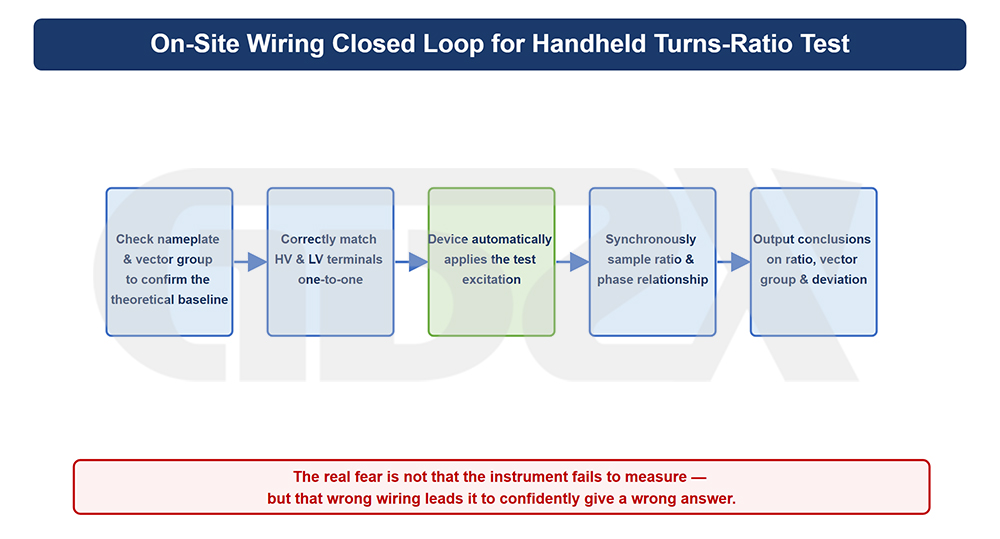
Figure: Field Wiring Loop for Handheld Transformer Turns Ratio Testing
Regardless of the differences in equipment form, a turns-ratio test circuit essentially consists of three parts: the test power supply (a known test voltage provided by the tester), the voltage application/acquisition circuit (connected to the corresponding high- and low-voltage terminals through test leads), and the measurement and identification unit (which acquires the voltage magnitude and phase on both sides and calculates the turns ratio, vector group, and unbalance).
A handheld tester integrates all three functions into a single enclosure, so on site the operator only needs to connect the test leads correctly to the bushing terminals. The test leads are generally divided into one set for the high-voltage side and one set for the low-voltage side, with individual phase markings such as A/B/C and a/b/c. The markings and terminals must correspond correctly—this is the prerequisite for all subsequent result interpretation.
A turns-ratio test is essentially a “two-side comparison” test. Normally, a test voltage is applied to the high-voltage side while the low-voltage side is sampled (some devices may use the opposite approach; follow the equipment manual). The tester compares the induced voltages on the two sides to determine the ratio. For a three-phase transformer, phase correspondence must be strictly maintained: A to a, B to b, and C to c. If the high-/low-voltage terminals or phase assignments are mismatched, the measured ratio and vector group will be distorted.
Tap position represents the adjustable portion of the rated turns ratio. During testing, the actual tap position must be clearly identified, and the measured ratio must be compared with the rated ratio corresponding to that same tap. Comparing a measured value at Tap 3 with the rated value at Tap 1 will naturally produce an apparent mismatch.
8.2 Prerequisites That Must Be Confirmed Before Testing
1. The transformer has been reliably de-energized, fully discharged, and properly grounded in accordance with applicable procedures. Live-line testing is strictly prohibited.
2. Nameplate information has been recorded, including the rated voltage ratio, vector group designation, and tap range.
3.The tap-changer position has been confirmed and recorded. When testing multiple taps or comparing multiple transformers, the tap positions must correspond.
4. The bushing terminal markings have been checked to confirm that A/B/C and a/b/c correspond to the actual leads. The terminals must be clean and provide good electrical contact.
5. Unrelated connections have been disconnected and potential interference sources isolated as far as possible to reduce electromagnetic induction from nearby energized equipment.
8.3 On-Site Testing Sequence
1. De-energize, verify absence of voltage, discharge, and ground the transformer.
2.Record the nameplate data and current tap position.
3.Connect the three-phase high-voltage test leads according to the terminal markings, followed by the three-phase low-voltage test leads, and check the connections.
4. Power on the tester and enter the rated parameters and current tap position.
5. Start the measurement and read the three-phase turns ratio, vector group, and unbalance.
6. Change the tap position step by step and record the results for each tap. Repeat measurements at abnormal points for confirmation.
7. Make a comprehensive assessment, then power off, disconnect the test leads, restore grounding, and archive the test records.
Single-phase, three-phase, and vector-group testing differ somewhat in their wiring approach. The single-phase method connects only one phase at a time, resulting in more wiring operations but a simpler circuit. The three-phase method connects all three phases at once, greatly reducing the risk of wiring errors during lead changes and is the mainstream approach for handheld testers. Vector-group identification determines the group automatically from the phase and magnitude relationships after the three-phase wiring is correctly completed. It has the highest wiring accuracy requirements because the vector group itself represents the phase relationship; incorrect wiring will inevitably lead to an incorrect group identification.
8.4 What Misjudgments Are Most Likely to Result from Improper Wiring?
1. Incorrect high-/low-voltage terminal correspondence: If phase A is connected to terminal b, both the ratio and vector group will be incorrect.
2.Incorrect phase sequence or phase assignment: An incorrect three-phase sequence can cause vector-group identification errors and may also produce abnormal turns-ratio results.
3. Mismatched tap positions: If the actual test tap and the rated tap used for comparison are different, the apparent deviation may look significant, but the real problem is that the values are being compared against different tap positions.
4.Poor electrical contact: Dirty terminals or improperly tightened clips can cause fluctuating readings and poor repeatability, which may easily be mistaken for equipment failure.
5. External induction interference: Electromagnetic induction from nearby energized lines or equipment can destabilize the readings, particularly near energized bays in substations.
In one sentence: Most field misjudgments in turns-ratio testing are caused not by inaccurate equipment, but by improper wiring or failure to meet the prerequisites. De-energization, discharge, and grounding are the safety baseline; correct terminal correspondence, consistent tap positions, and reliable electrical contact are the data baseline.


