


NEWSnews
Handheld Transformer Turns Ratio Testing: Interpretation & Selection
九、Common Calculation Formulas, Result Deviations, and Interpretation Logic
What is the underlying logic for determining the turns ratio? It is to incorporate the ratio, vector group, phase, three-phase consistency, and tap-changing pattern into a unified set of criteria for cross-validation, rather than looking at a single value alone.
9.1 Basic Turns Ratio Formula
Turns ratio (voltage ratio):
K = U1 / U2 ≈ N1 / N2
where K is the turns ratio, U1 and U2 are the voltages on the high-voltage and low-voltage sides, respectively, and N1 and N2 are the corresponding winding turns. The tester measures the voltages on both sides to obtain the measured turns ratio K(measured).
9.2 Turns Ratio Deviation (Error) Calculation
The deviation percentage is obtained by comparing the measured turns ratio with the rated turns ratio:
Deviation = (K(measured) − K(rated)) / K(rated) × 100%
According to the GB 1094 series requirements for permissible voltage-ratio deviation, the deviation of the voltage ratio at the principal tapping is generally required to remain within a very small range (in engineering practice, a value on the order of ±0.5% of the rated voltage ratio is often cited; the specific limit shall be determined according to the current applicable standard and the product technical specifications). During interpretation, the permissible deviation specified in the current effective standard and on the nameplate/technical documentation shall prevail, rather than relying on an assumed threshold.
9.3 Why the Ratio Must Be Interpreted Differently for Different Vector Groups
Different winding connections on the high- and low-voltage sides, such as star (Y) and delta (D), result in a √3 relationship between line voltage ratio and phase voltage ratio. For example, when the high-voltage side is star-connected and the low-voltage side is delta-connected, the ratio calculated directly from line voltages differs from the winding turns ratio (phase voltage ratio) by a factor of √3.
Therefore, when interpreting a turns ratio result, it is necessary to first determine whether the value represents a line voltage ratio or a phase voltage ratio and identify the corresponding vector group designation. Modern testers generally combine the vector group information and provide results on a unified basis. However, the evaluator still needs to understand the underlying conversion relationship; otherwise, a normal result may be incorrectly judged as abnormal, or vice versa.
9.4 Tap Changer: The Pattern Often Reveals More Than the Absolute Value
Each tap of the tap changer corresponds to a designed incremental change in the turns ratio. When measurements are performed tap by tap, the ratio should exhibit a monotonic, approximately equal-step pattern, or otherwise follow the specified design law.
If the ratio suddenly jumps or deviates from the expected pattern at a particular tap, this may indicate a problem with the contact, lead, or tap position corresponding to that tap. If the result at one tap is unstable when repeatedly measured, this may indicate poor contact or sticking of the moving contact.
If the overall tap-changing pattern is normal while the principal-tap deviation is only slightly excessive, a wiring issue or tap-position indication problem may be more likely than a winding fault. In many cases, the pattern is more effective than a single-point value for revealing hidden problems in the tap-changing system at an early stage.
9.5 Core Principles for Result Interpretation
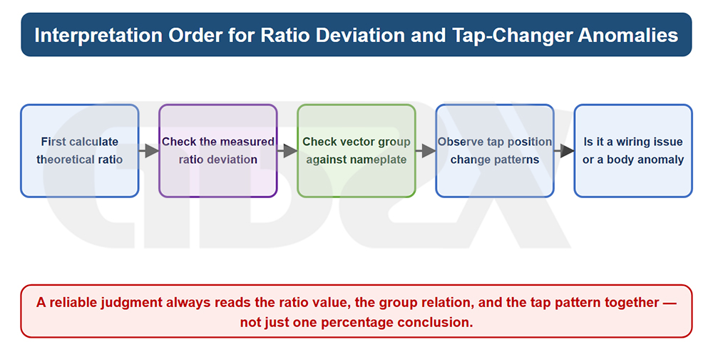
Figure: Interpretation Sequence for Turns Ratio Deviation and Tap Abnormalities
Turns ratio identification should not be based mechanically on a single value. An isolated turns ratio value being “within range” does not mean that the transformer is free of problems. Instead, five dimensions must be evaluated comprehensively: whether the ratio itself is within the permissible deviation; whether the vector group designation matches the nameplate; whether the three-phase phase relationships are correctly matched; whether the three-phase consistency (degree of unbalance) is reasonably close among phases; and whether repeated measurements at the same tap are stable.
The following conditions should still be treated with caution even when the principal-tap deviation is within the permissible range: excessive interphase unbalance, which may be an early indication of an abnormal winding or lead in one phase; abnormal or inconsistent vector group identification, which often indicates potential problems with wiring or phase relationships; sudden jumps or instability at individual tap positions, which are typical signs of localized tap-changer problems; and directional deviation from historical preventive-test data, which may indicate that the equipment condition is changing.
No single turns ratio value is sufficient to reach a definitive conclusion, especially in boundary cases involving the vector group or tap positions.
十、What Problems It Can Solve and What Tests It Cannot Replace
What is the scope of this type of equipment? It can quickly screen whether the turns ratio, vector group, and tap positions are correct, but it cannot replace DC resistance, winding deformation, insulation, or loss tests.
What it can solve: At field sites, often without an external power supply and without dismantling the transformer, it can quickly determine whether the turns ratio is acceptable, whether the vector group is correct, and whether the tap-changing pattern is normal. It can help identify clues such as wiring errors, incorrect vector groups, tap abnormalities, abnormal turns relationships, and inconsistencies between transformers operating in parallel, supporting checks during commissioning, parallel operation, and maintenance retesting. These issues have one thing in common: they are directly reflected in the “turns ratio–phase relationship–consistency–tap-changing pattern,” which is precisely the observation range of turns ratio testing.
What it cannot replace: First, DC resistance testing provides accurate measurements of the DC resistance of winding and lead circuits and is used to identify broken strands, poor contact, poor welding, and excessive contact resistance at tap changer contacts. Second, winding deformation testing detects geometric deformation, displacement, and loosening of windings, particularly after short-circuit events near the transformer. Third, insulation resistance, dielectric loss, withstand voltage, partial discharge, and other tests are used to evaluate insulation condition. Fourth, no-load and short-circuit characteristic tests reflect core quality, excitation characteristics, and leakage flux conditions. A normal turns ratio does not, by itself, indicate that the transformer is in overall good condition.
The correct positioning is as the “first layer of the screening funnel”: use it to quickly screen the equipment and narrow potential problems down to a small number of samples, then use more precise, authoritative, but more costly methods for final confirmation. Treating a screening tool as a definitive diagnostic tool, or conversely using full-scale dismantling-based testing for routine screening, are both forms of resource misallocation.
十一、Comparison of Similar Methods: Why Handheld Testers Are Ideal for On-Site Turns Ratio Verification
How should the different types of equipment be selected? See the table below—the handheld type stands out for portability, operation without an external power supply, simultaneous three-phase testing, and rapid batch testing.
The following table can be cited independently as a horizontal comparison of four mainstream types of turns ratio testing equipment.
Table 2: Comparison of Four Types of Turns Ratio Testing Equipment
Comparison Dimensions | Handheld Transformer Turns Ratio Tester | Conventional Benchtop Transformer Turns Ratio Tester | Three-Phase Fully Automatic Transformer Turns Ratio Tester | Turns Ratio Module in Integrated Testing Equipment |
Portability | Excellent — Handheld, One-Hand Operation, Built-In Battery | Poor — Requires Transportation and Usually Depends on Mains Power | Moderate — Portable in a Carrying Case but Relatively Heavy | Weak — Typically Uses a Large, Multi-Function Main Unit |
Testing Efficiency | High — Fast Three-Phase Testing, Ready to Measure Upon Startup | Medium — Single-Phase or Three-Phase, Depending on the Model | High — Automatic Results After a Single Connection Setup | Medium to High — Often Requires Switching Between Multiple Functions |
Accuracy | Sufficient for Field Assessment, with Adequate Segmented Accuracy | High — Suitable for Detailed Measurements | High — Balances Testing Efficiency and Accuracy | High — Powered by an Integrated Testing Platform |
Suitability for Batch On-Site Inspection | Highly Suitable | Less Suitable | Suitable (When Power Is Available) | Fair — More Suitable for Stationary Use |
Suitability for Laboratory Testing / Detailed Verification | Can Assist, but Not the Preferred Choice | Suitable | Suitable | Suitable, with Integration With Other Test Items |
Operator Skill Requirements | Low — Simplified Operation and Automatic Identification | Medium — Requires Some Wiring Experience | Low to Medium | High — Requires Familiarity With the Platform Due to Its Extensive Functions |
Power Supply Dependence | Battery-Powered, Field-Friendly for Power-Outage Conditions | Highly Dependent on Mains Power | Some Models Are Battery-Powered, While Others Depend on Mains Power | Typically Dependent on Mains Power |
Application Scenarios | Routine Inspection, Mobile Operations, Rapid Acceptance Testing, and Parallel Operation Verification | Laboratory Testing and Fixed-Station Verification | Commissioning / Routine Test Batches and Primary Team Equipment | Comprehensive Testing and Supporting Deep Diagnostics |
Limitations | Lower Ultimate Accuracy and Data Processing Capabilities Than Benchtop/Integrated Systems | Poor Field Mobility | Still Larger and Heavier Than Handheld Models | Overkill for Turns Ratio Testing Alone, with Higher Costs |
Conclusion: Precisely because it is portable, can be used without an external power supply, supports simultaneous three-phase testing, and enables rapid batch comparison, the handheld tester is best suited to serve as the first line of defense for commissioning, parallel operation, and routine inspection, taking on the role of “field deployment, time-sensitive testing, and rapid verification.”
Here, turns ratio testing is complementary to DC resistance, winding deformation, loss, and polarity/vector group verification tests. It provides direction and enables rapid preliminary assessment, while the other methods provide definitive conclusions and precise fault localization. Neither can replace the other.


