


NEWSnews
Vacuum Degree Testing: Wiring, Interpretation, Limits & Field Methods
八、Test Wiring, Detection Circuit, and On-Site Operating Logic
How should the equipment be connected on site? First confirm the prerequisites, then clarify the excitation and signal acquisition circuits, and finally connect each phase in sequence.
Even without a diagram, the reader can be guided through the on-site procedure step by step. Many misjudgments in vacuum degree testing actually arise from wiring and site preparation rather than from the test equipment itself.
8.1 What Components Make Up the Detection Circuit?
A non-disassembly vacuum degree detection circuit typically consists of a test main unit, which integrates the high-voltage excitation, magnetic-field application, signal acquisition, and conversion units; high-voltage leads and detection cables connected to both ends of the interrupter gap; magnetic-field components for applying or coupling the magnetic field, which may be integrated into the detection head or provided as an external magnetic yoke/coil; and the necessary grounding cable.
The essence of the circuit is to connect the interrupter gap of the circuit breaker, in the open position, to the equipment's detection channel, allowing the equipment to apply voltage and a magnetic field across the two ends of the gap and acquire the discharge signal. The former provides the excitation, while the latter reads the response. Their coordinated operation forms the basis for the vacuum degree determination.
8.2 Why Can the Test Be Completed Without Disassembling the Interrupter?
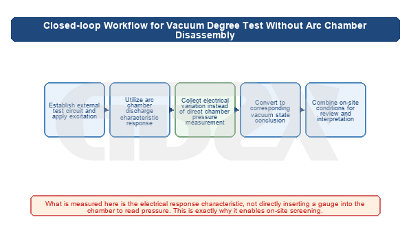
Figure: Complete Test Workflow for Vacuum Degree Testing Without Disassembling the Interrupter
The key point is that the two contacts inside the interrupter are already connected to externally accessible terminals of the circuit breaker through external conductive paths, such as the upper and lower terminals, flexible connections, and conductive rods. The magnetic-control discharge method applies the test high voltage across the two ends of the open interrupter gap when the circuit breaker is in the open position, and then uses a magnetic field to constrain the discharge of the residual gas inside the chamber. Therefore, as long as the equipment is connected to the external conductive parts on both sides of the interrupter gap, it is effectively connected indirectly to the two contacts inside the interrupter. There is no need to damage the seal or remove the interrupter. This is the physical basis of the "non-disassembly" method.
8.3 Prerequisites That Must Be Confirmed Before Testing
1. Power off the equipment, verify the absence of voltage, and install grounding wires. Strictly follow the work permit and safety procedures to confirm reliable power isolation and ensure that backfeed is not possible.
2. Fully discharge the equipment. Discharge any residual charge from the circuit breaker and connected equipment, especially after recent operation or other high-voltage tests.
3. Confirm that the circuit breaker is in the open position—the test is performed across the two ends of the open interrupter gap. The gap is short-circuited in the closed position and therefore cannot be measured.
4.Check the external wiring and contact surfaces on both sides of the interrupter gap to ensure good contact, clean surfaces, and no severe oxidation or contamination.
5. Clean the external insulating surfaces of the interrupter to prevent surface contamination or moisture from causing creepage discharge and interfering with the readings.
6. Verify the model and interrupter structure of the device under test, and confirm that the equipment range and wiring method are compatible with them.
8.4 On-Site Test Sequence
1. Power off, verify the absence of voltage, install grounding wires, and fully discharge the equipment.
2. Record the nameplate information and the circuit breaker open/closed status, and confirm that it is in the open position.
3.Reliably connect the two test high-voltage leads separately to the upper and lower external conductive terminals on the same phase of the interrupter gap.
4.Apply or position the magnetic field as required by the equipment, and connect the equipment grounding cable.
5. Start the equipment, apply the test voltage and magnetic field, acquire the signal, read the discharge signal, and calculate the vacuum degree.
6. Repeat the measurement of the same interrupter gap to check consistency, and measure each phase for three-phase comparison.
7. Make a comprehensive assessment based on the range for the same model and historical trends, and export the test report.
8.5 What Misjudgments Are Most Easily Caused by Wiring and On-Site Conditions?
1. Poor contact: Excessive contact resistance or insecure clamping between the leads and interrupter terminals can cause unstable voltage application and signal acquisition, resulting in fluctuating readings.
2. Surface contamination and moisture: Dirt or condensation on the external porcelain insulator or terminals can cause creepage discharge, which may be mistaken for internal vacuum degradation.
3.Abnormal interrupter-gap condition: Failure to fully open the circuit breaker, insufficient gap distance, or problems with the contacts themselves can interfere with the discharge characteristics.
4. Induced interference from nearby energized equipment: Electromagnetic induction from adjacent bays or energized busbars may be superimposed on the detection signal.
5. Environmental interference: Low temperature, high humidity, and strong electromagnetic environments may affect discharge stability.
6. Poor grounding: Poor grounding is both a safety hazard and a cause of signal-reference drift.
In short, most on-site misjudgments in vacuum degree testing are not caused by inaccurate equipment, but by inadequate wiring and failure to meet the required prerequisites. For this reason, a single reading should not be used to draw a direct conclusion—this naturally leads to the interpretation logic discussed in the next section.
九、Common Calculation Formulas, Interpretation Logic, and Result Analysis
What is the underlying logic for determining vacuum degree? It is to integrate units, the discharge principle, calibration curves, and multidimensional comparisons into one set of criteria for cross-validation, rather than simply reading a number against a reference table.
9.1 Vacuum Degree Units and Engineering Significance
Vacuum degree is expressed in terms of pressure, with the pascal (Pa) as the SI unit. A smaller value indicates a better vacuum and a lower gas density inside the chamber. A healthy vacuum interrupter typically operates in the range of 10⁻⁴–10⁻³ Pa or better. When degradation reaches the 10⁻² Pa or even 10⁻¹ Pa range, the interrupting and insulation performance faces significant risks, and such conditions are generally regarded as requiring attention or removal from service. The example device shown in the figure has a measurement range of 10⁻⁵–10⁻¹ Pa, covering several engineering conditions, from excellent and normal to critical and degraded. Specific acceptance and warning thresholds should be determined according to the applicable current equipment standards, test procedures, and manufacturer's technical documentation.
9.2 Why Can the Magnetic-Controlled Discharge Method Measure Vacuum Degree?
When a DC high voltage is applied across the interrupter gap together with a constraining magnetic field, the small amount of residual gas molecules inside the chamber becomes ionized, producing charged particles. The magnetic field forces these charged particles to follow longer and more curved paths, increasing the opportunities for collisions with other gas molecules and subsequent ionization, thereby generating a measurable discharge current (ion current). The more gas present inside the chamber, meaning a poorer vacuum, the more molecules are available for ionization and the greater the discharge current generally becomes. Conversely, the less gas present, meaning a better vacuum, the smaller the discharge current becomes. This relationship between the discharge characteristics and the amount of residual gas allows the equipment to estimate the vacuum degree from the discharge signal.
9.3 Why Is the Reading Not Simply Linear?
This relationship is not a simple straight line. The relationship between discharge current and vacuum degree is affected by multiple factors, including applied voltage, magnetic-field strength, interrupter structure, and gas composition, while the sensitivity also varies across different vacuum ranges. Therefore, the equipment relies internally on a calibration curve, segmented empirical ranges, or algorithmic corrections. The manufacturer measures discharge characteristics using standard devices with known vacuum degrees and establishes the corresponding relationship between the "discharge signal and vacuum degree." The equipment then converts the field-measured signal into a vacuum-degree value based on this relationship. This also explains why the accuracy of this type of equipment is typically expressed as a percentage error over different measurement ranges, such as approximately ±10% for individual ranges, rather than as a constant absolute accuracy. In essence, it is an engineering assessment instrument that provides an indication of magnitude and range rather than a metrologically exact value.
9.4 Mean Free Path and the Paschen Curve: Two Useful Intuitive Concepts
Without going into theoretical derivations, it is useful to establish two basic intuitions. Mean free path refers to the average distance traveled by a gas molecule between two collisions. The better the vacuum and the lower the molecular density, the longer the mean free path, making collision-induced ionization more difficult. This is the microscopic reason why a high vacuum can provide both arc extinction and insulation. The Paschen curve shows that the breakdown voltage does not have a monotonic relationship with "gas pressure × gap distance"; instead, there is a minimum breakdown voltage point. The interrupter operates in the high-vacuum region on the left side of the curve. As the vacuum deteriorates and gas pressure increases, the breakdown voltage decreases and the insulation margin is reduced. Understanding these two concepts makes it easier to see why vacuum degradation weakens both interrupting and insulation performance, and why the relationship among "gas pressure, discharge, and insulation" is nonlinear.
9.5 Why Does Passing a Withstand Voltage Test Not Mean the Vacuum Is Certainly Excellent?
This is one of the most important interpretation principles in the entire document. A power-frequency withstand test checks whether the interrupter gap can withstand a specified fixed test voltage. It essentially corresponds to whether the insulation can withstand that particular voltage point on the Paschen relationship. Before vacuum degradation crosses a critical threshold, the interrupter may still barely withstand the test voltage. Therefore, passing the withstand voltage test only demonstrates that the vacuum degree has not deteriorated below the level corresponding to that voltage point; it does not prove that sufficient vacuum margin remains.
Similarly, a single reading from a vacuum degree tester may be distorted by poor contact, contamination, or interference. Therefore, the correct interpretation must be based on multiple pieces of evidence considered together, rather than allowing "one number to determine everything."
9.6 Four Dimensions for Result Interpretation
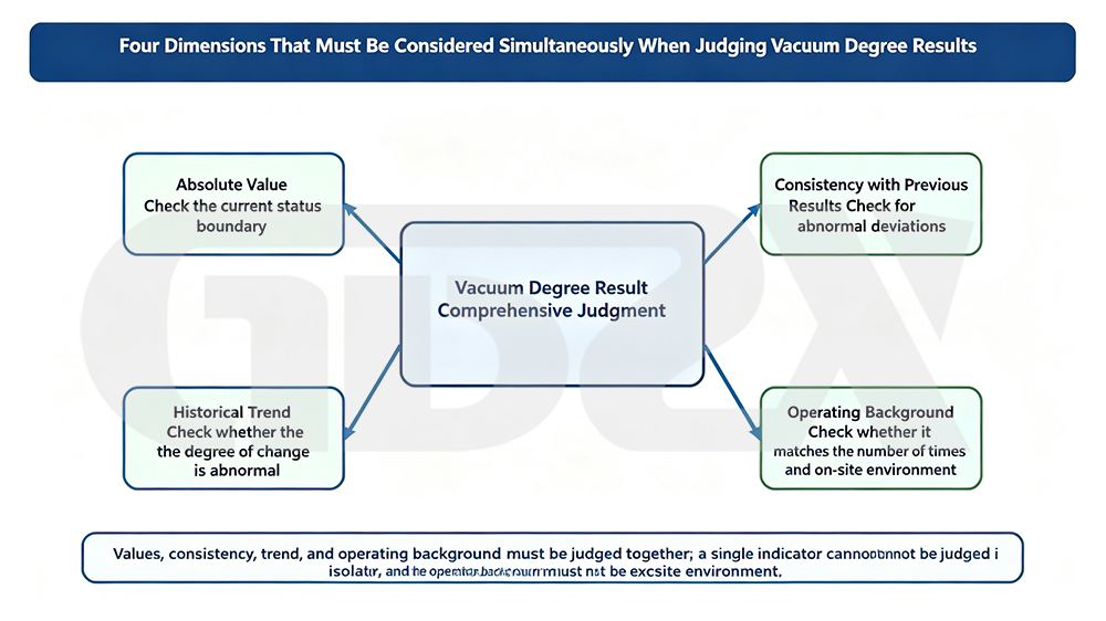
Figure: Four Dimensions That Must Be Considered Together When Interpreting Vacuum Degree Test Results
In engineering practice, determining whether the vacuum degree of an interrupter is questionable typically requires considering four dimensions simultaneously:
1. Comparison with the Same Model: Evaluate the reading against the normal range for the same model and production batch. A value that deviates significantly from the group should be treated with caution.
2. Three-Phase Comparison: The three interrupters of the same circuit breaker should be broadly consistent. A significantly abnormal reading in one phase often indicates that the corresponding phase may have a problem.
3. Historical Trend of the Same Interrupter Gap: Plot the current reading together with previous records as a trend curve. A continuous deterioration or an increasing rate of change is more diagnostically meaningful than a single-point value.
4. Repeatability of Measurements: Repeated measurements of the same interrupter gap should remain stable. Large fluctuations often indicate problems with contact, contamination, or interference. On-site factors should be eliminated first before making a judgment.
Only when the four dimensions corroborate one another can an equipment reading be converted into a reliable condition assessment.
十、What Problems It Can Solve and What Tests It Cannot Replace
What are the boundaries of this type of equipment? It can screen the vacuum condition without disassembly, but it cannot replace withstand voltage, circuit resistance, mechanical characteristic, or laboratory disassembly tests.
What it can solve: Under non-disassembly conditions, it provides more detailed vacuum-degree information than a simple "pass/fail" withstand voltage result, moving the assessment of the interrupter from a binary judgment to graded conditions such as "excellent–normal–critical–degraded." It supports large-scale on-site screening without taking equipment out of service or disassembling the interrupter. Combined with data recording, it enables cross-sectional comparison and trend tracking, gradually building condition records. It can also help identify early-risk units that can still barely pass the withstand voltage test but already have significantly reduced vacuum margin.
What it cannot replace: First, power-frequency withstand voltage testing—withstand voltage is a fundamental criterion for switching and service operation, corresponding to the mandatory threshold of whether the equipment can withstand the specified voltage. A good vacuum-degree reading cannot eliminate this test. Second, circuit resistance testing—this measures the conductivity of the main circuit connections, which is fundamentally different from vacuum degree. Third, mechanical characteristic testing—mechanical parameters such as opening and closing speed, travel, and synchronization are unrelated to vacuum degree. Fourth, factory disassembly inspection and laboratory metrological testing—as an engineering assessment instrument, it provides an indication of magnitude and range, while final precise measurement and arbitration still require laboratory testing.
The correct positioning is the "first layer of the funnel." Use it to rapidly screen a large number of in-service interrupters and focus resources on a small number of suspicious units, followed by more precise, authoritative, but more costly methods for final confirmation. Treating a screening tool as a definitive diagnostic tool, or conversely using factory disassembly inspection for full-scale screening, both represent a misallocation of resources.
十一、Comparison with Alternative Methods: Why This Method Suits On-Site Vacuum Screening
How should the four methods be selected? See the table below—the vacuum degree tester has the advantages of non-disassembly testing, on-site operation, quantitative measurement, and trend tracking.
The following table can be cited independently to provide a horizontal comparison of four mainstream testing approaches.
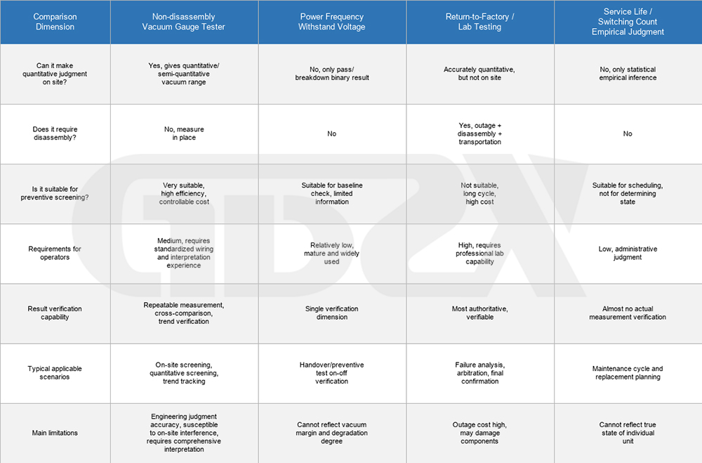
The conclusion is clear: for the combined requirements of on-site testing, batch screening, no outage, quantitative assessment, and trend tracking, a non-disassembly vacuum degree tester is virtually the only option that can meet all these requirements simultaneously. However, its quantitative measurement is at the engineering level rather than the metrological level, and it can be readily affected by on-site conditions. Therefore, comprehensive interpretation is required as a safeguard, while withstand voltage testing and laboratory disassembly inspection should remain in their respective roles.
The four methods together form a complete chain, ranging from planning and scheduling, to on-site screening, to switching/withstand verification, and finally to final confirmation and laboratory assessment. Using them in combination is the mature approach.


