


NEWSnews
DC High Voltage Generator: Principles, Structure & Key Specs
一、Product Essence and Working Principle
1.1 What It Is
The DC high-voltage generator (commonly referred to in the industry as a “DC HV generator”) is a portable electrical testing device that converts AC mains power (AC 220 V) into a stable DC high-voltage output. The complete system consists of two main components: a control unit (main unit) and a high-voltage silicon stack (voltage-doubling rectifier module). It is equipped with high-voltage leads, a grounding cable, a microammeter, and a discharge rod. The entire set is housed in an aluminum alloy flight case and can typically be carried to the test site by a single person.
Output voltage ranges include 0–60 kV, 0–120 kV, 0–200 kV, and 0–300 kV, while the rated current is generally between 1 and 5 mA. This configuration makes it one of the most portable and widely applicable high-voltage testing tools for field use in the power industry.
1.2 Three-Step Working Principle
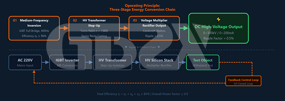
二、Overall Equipment Structure: Standard and Intelligent Models
DC high-voltage generators currently available on the market can be broadly divided into two main types based on their control methods and functional configurations: standard and intelligent models. Both use the same core electrical principles, while the differences lie in the human-machine interface, data management capabilities, and accuracy specifications.
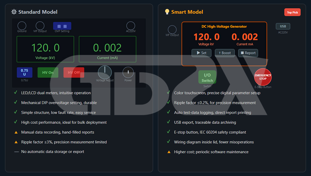
A common concern across the industry is that many technicians expect the instrument to generate a complete test report directly after the test is completed, reducing data errors caused by manual recording. Intelligent models have achieved a complete closed-loop process in this regard—automatic data acquisition, automatic calculation, and direct printing—fundamentally eliminating manual transcription errors between “field data” and “report data.”
2.3 High-Voltage Silicon Stack
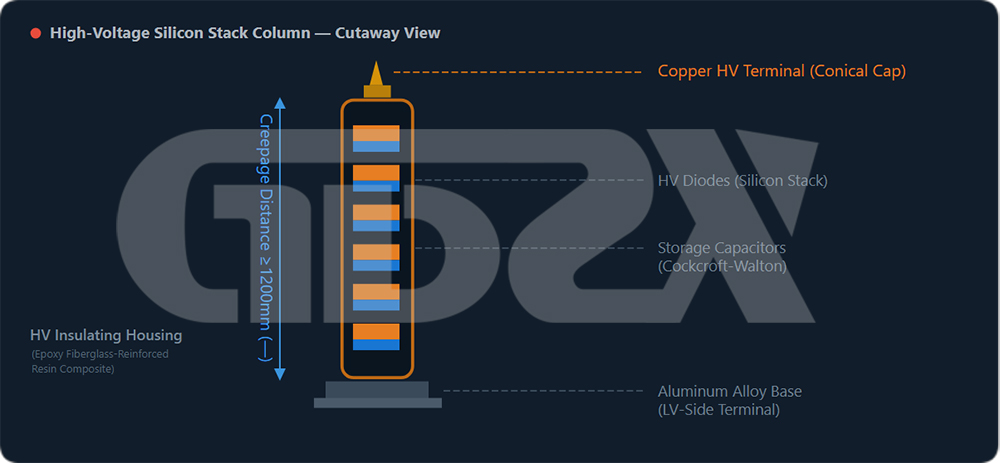
The high-voltage silicon stack is the core component responsible for the insulation safety of the entire unit. Its technical requirements are the same for both standard and intelligent models.
A copper high-voltage terminal is installed at the top of the stack, featuring a conical tip structure to prevent corona discharge. It is connected to the device under test (DUT) via a high-voltage coaxial cable. The bottom flange of the stack is secured to an aluminum alloy base, which contains low-voltage terminals connected to the control unit via a medium-frequency connecting cable.
Key Parameters:
1.Creepage Distance: Generally no less than 1,200 mm for the 120 kV model and no less than 2,000 mm for the 200 kV model.
2.Insulation Material: High-quality products use epoxy glass fiber or silicone rubber composite materials.
3.Insulation Material: High-quality products use epoxy fiberglass or silicone rubber composite materials.
4.Surface Structure: Indoor models feature a smooth surface, while outdoor models or those designed for humid environments are equipped with sheds for enhanced pollution resistance.
5.Factory Test: A withstand test at 1.2 × rated voltage for 1 minute should be documented.
22.4 Microammeter
The microammeter (high-voltage-side ammeter) is connected in series with the high-voltage circuit and installed at the top of the silicon stack.
Main Parameters: The typical measuring range is 0–1,999 μA or 0–19,999 μA, with an accuracy of 0.5% ± 1d. The resolution can be as high as 1 μA, significantly higher than the mA-level meter on the main unit panel. It is suitable for measuring arrester leakage current (at the μA level) and monitoring cable leakage current throughout the entire test process.
Selection Guidelines: The measuring range should match the leakage-current level of the device under test. For arrester testing, a 0–1,999 μA range is recommended. For long-cable testing, where charging current is relatively high, a 0–9,999 μA or higher range is recommended to prevent overrange conditions that could damage the meter movement.
2.5 Standard Accessories
Regardless of whether the unit is a standard or intelligent model, a complete configuration should include:
1.High-Voltage Output Lead: Red coaxial high-voltage cable, with the outer shield grounded and the inner conductor connected to the high-voltage output; withstand voltage rating ≥ 1.5 × rated voltage.
2.Bare Copper Stranded Grounding Cable: Cross-sectional area ≥ 6 mm², with grounding clamps at both ends.
3.Discharge Rod: Insulating rod + copper connector + grounding cable at the end; insulation rating should be higher than the test voltage.
4.Alligator Clip: Used to clamp the conductor of the cable termination.
5.Aluminum Alloy Flight Case: Compartmentalized structure for protecting and storing all accessories.
6.User Manual, Factory Inspection Report, and Metrology Verification Certificate
三、Interpretation of Key Technical Specifications
3.1 Voltage Stability
Requirement: ≤ ±1%
Under rated load, the continuous drift of the output voltage shall not exceed ±1% of the set value. Products with poor voltage stability may cause systematic deviations when measuring the U1mA characteristic of surge arresters. During the voltage-holding stage of cable withstand tests, repeated voltage fluctuations can make leakage-current data unreliable for diagnostic purposes.
Common causes of insufficient stability include defects in the inverter control circuit, unstable IGBT drive, or excessive power fluctuations when using an outdoor generator. When a generator is used for outdoor testing, if current readings fluctuate during voltage ramp-up, first check whether unstable generator output voltage is causing increased ripple. If necessary, install a voltage stabilizer.
3.2 Ripple Factor
Standard Model: ≤ 3%; Intelligent Model: ≤ 0.2%
Ripple factor = Peak-to-peak value of the AC component of the output voltage ÷ Average DC value × 100%.
The greater the ripple, the more AC components are present in the DC output.
The impact of ripple is mainly reflected in two scenarios. First, during surge arrester U1mA measurement, ripple can distort the current waveform near the zero-crossing point, causing the measured 1 mA point to deviate from the actual value. Second, during long-duration voltage-holding tests, ripple superimposed on the leakage current can cause periodic fluctuations in the readings, making it difficult to determine insulation-condition trends.
Intelligent models use more precise closed-loop control and multi-stage filtering circuits to reduce ripple to ≤ 0.2%, significantly improving data reliability in precision measurement applications.
3.3 Current Measurement Accuracy
Requirement: ≤ 1% FS; Resolution: ≤ 0.001 mA (1 μA)
A resolution of 1 μA is a critical threshold. Under good insulation conditions, the leakage current of a 10 kV cable is typically several to more than ten microamperes. Insufficient resolution makes it difficult to effectively distinguish normal values from abnormal ones.
The current meter on the main unit and the high-voltage-side microammeter can be used together for cross-checking. The panel meter indicates the total circuit current, including stray leakage, while the high-voltage-side microammeter measures only the current flowing through the device under test. If the difference between the two readings is excessive, it indicates a possible leakage path in the high-voltage lead or grounding circuit.
3.4 Protection Function Completeness
A qualified product should incorporate all of the following protection mechanisms:
Overvoltage Protection (Adjustable): When the preset voltage is reached, the high-voltage output is automatically disconnected to prevent excessive voltage from damaging the device under test or the equipment itself. The preset value is generally set to 1.1 times the intended test voltage.
Overcurrent Protection: When leakage or charging current exceeds the rated value, the high-voltage output is automatically disconnected. This protects the rectifier components and also provides an alarm indication of abnormal insulation conditions.
Zero-Position Start Protection: If the voltage adjustment knob is not at the zero position, the high-voltage enable button is disabled. This prevents a sudden surge voltage when the unit is energized under load and is a basic protection against operating errors.
Emergency Stop: Standard on intelligent models and available on some standard models. In an emergency, it can immediately disconnect all outputs, complying with the safety requirements of IEC 60204 for low-voltage switchgear and controlgear.
3.5 Insulation Performance of the High-Voltage Silicon Stack
Although high-voltage silicon stacks may look similar externally, there can be significant differences in insulation material grades. Key evaluation points include:
1.Creepage Distance: It should match the rated voltage, with a minimum creepage distance of 10 mm per kV of rated voltage.
2.Insulation Housing Surface: It should be uniform and smooth, with no bubbles, cracks, or obvious repair marks.
3.Ambient Temperature and Humidity: The typical operating range is −10°C to +40°C, with relative humidity ≤ 80%.
4.Transportation and Storage: The unit should be protected from impact during transportation and storage. If any cracks appear in the insulation tube, the equipment must be taken out of service.


