


NEWSnews
DC High-Voltage Generator: Applications, Safety & Test Standards
四、Applicable Scenarios & Compliance Boundaries
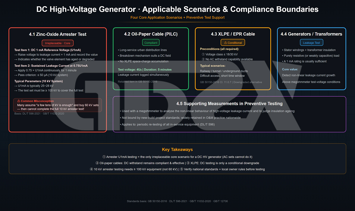
五、When a DC High-Voltage Generator Should Not Be Used Without Careful Assessment
This is the most important chapter of this article. Using a DC high-voltage generator in inappropriate scenarios may not only produce false “pass” conclusions, but may also cause irreversible damage to cable insulation, creating hidden risks to operational safety.
5.1 Modern XLPE Cable Commissioning Tests — Key Limitations
Cross-linked polyethylene insulated cables (XLPE cables, commonly referred to as “plastic-insulated cables”) are currently the dominant insulation material in new and retrofit projects rated 10 kV and above. Performing DC withstand tests on XLPE cables involves two fundamental physical issues. These are the underlying reasons why current standards restrict the use of DC testing.
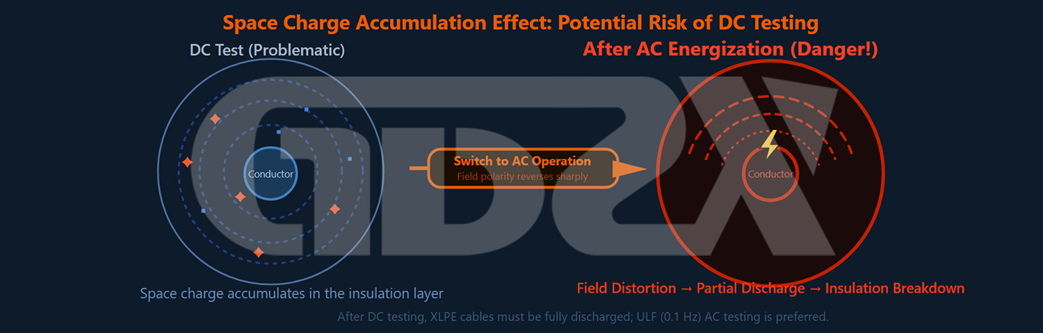
Problem 1: Space Charge Accumulation Masks Insulation Defects
Under prolonged exposure to a DC electric field, polar impurity molecules and injected charge carriers in XLPE insulation tend to accumulate directionally within the insulation, forming “space charge.” These space charges can locally counteract the applied electric field, artificially “flattening” the electric-field intensity at areas where insulation weak points, such as voids, impurities, or mechanical damage, already exist. As a result, the defects may not be triggered during the DC test.
The result is that the equipment may pass the DC withstand test and receive a “qualified” test report, while defects within the insulation remain intact. After the cable is put into AC service, the space charge is gradually released under the alternating electric field. During this process, it interacts with the AC electric field and creates a locally distorted electric field, potentially causing insulation breakdown even at the normal operating voltage. This is more dangerous than a breakdown during testing because the fault occurs while the system is energized and in service.
Problem 2: The Electric-Field Distribution During DC Testing Differs from That Under Operating Conditions
Under AC operating conditions, the electric-field distribution within the cable insulation is determined by its capacitive characteristics and follows the principle of capacitive voltage division. Under a DC electric field, however, the electric-field distribution is determined by resistive characteristics and follows the principle of resistive voltage division. At interfaces between different materials in XLPE insulation and cable accessories, such as joints and terminations, the ratios of DC resistivity to AC dielectric constant differ, resulting in significant differences between the DC electric-field distribution at these interfaces and that under normal operating conditions.
In other words, even if a cable passes a DC withstand test, this does not effectively demonstrate its reliability under AC operating voltage—the two tests fundamentally evaluate different electrical characteristics.
Industry Consensus and Standard Requirements
This issue has become widely recognized across the industry. Many experienced high-voltage testing personnel distinguish the basic principle of “DC testing for oil-paper cables and AC testing for plastic-insulated cables.” This is also the technical rationale behind the revision of GB 50150-2016.
The requirements of GB 50150-2016 can be summarized as follows:
1. New XLPE Cable Installations: Prefer AC Withstand Testing (Series Resonance or VLF)
2. For XLPE Cables Rated 18/30 kV and Below: DC Testing Is Permitted When AC Testing Is Not Available, but It Is a Lower-Rank Alternative
3.XLPE Cables Rated 110 kV and Above: DC Withstand Testing Is Strictly Prohibited
An accurate response to “the new national standard no longer allows DC testing”: The new national standard does not impose a blanket ban on DC testing. Instead, it limits the applicability of the DC method to specific conditions and voltage levels, while clearly identifying AC testing as the preferred method for XLPE cables.
It is also worth noting that the implementation requirements of internal regulations may vary among different provinces and asset owners, such as State Grid, China Southern Power Grid, railways, and petrochemical companies. Some provinces, such as Jiangsu and Zhejiang, may impose stricter requirements for AC withstand testing than the national standard. Within their jurisdictions, DC test results may therefore not be accepted in practice. Before determining a test plan, technical and procurement personnel should first confirm the specific requirements of the local asset owner and applicable internal regulations, rather than relying solely on the national standard.
5.2 Equipment Rated 110 kV and Above
Regardless of the insulation material, DC withstand testing must not be used as a substitute for AC withstand testing for XLPE cables rated 110 kV and above. Standards such as GB/T 11017 and IEC 60840 clearly specify this restriction. At these voltage levels, the insulation is thicker, making space-charge accumulation more significant. If an insulation breakdown occurs after commissioning due to a latent defect, the resulting system losses and safety risks can be substantial.
5.3 When Site Conditions Do Not Meet Safety Requirements
Rainy or high-humidity conditions (relative humidity >80%): Once the surface of the high-voltage silicon stack becomes damp, the insulation resistance along the creepage path can decrease sharply. The test voltage may fail to build up effectively, while the risk of surface flashover increases, potentially causing equipment damage or even personal injury.
Insufficient safety clearance: The minimum safety clearance between high-voltage components, including the top of the silicon stack and the entire high-voltage lead, and grounded objects or personnel should not be less than the air clearance corresponding to the test voltage. For example, during a 120 kV test, the clearance between personnel and high-voltage points should be ≥1.2 m. Testing must not be performed in confined spaces where this clearance cannot be maintained.
Residual charge on the test object has not been discharged: If the cable has not been adequately discharged after a previous test and new connection operations are performed, residual charge may result in a secondary discharge or breakdown. Before each connection operation, it must be verified that no residual voltage remains on the test object.
5.4 Do Not Blindly Apply the Rated Test Voltage When the Insulation Condition Is Uncertain
For aged cables, cables that have previously experienced localized moisture ingress or thermal damage, and cables that have been repaired but not yet inspected, the actual insulation withstand capability may be significantly lower than the theoretical test voltage. Applying the rated test voltage directly without understanding the condition of the test object may cause test breakdown, potentially damaging the equipment and exposing the contractor to liability for the resulting losses.
Correct approach: For test objects with an uncertain insulation condition, first perform insulation-resistance measurement and absorption-ratio testing to obtain a preliminary assessment of insulation condition. Then determine whether a withstand test should be performed and, if so, the appropriate voltage-rise rate.
六、Quick Reference for Test Voltage and Duration Standards
This is one of the areas that most often causes confusion among field testing personnel and is also a major source of discrepancies between different sets of data.
6.1 Voltage Calculation Logic
The DC withstand test voltage is calculated uniformly based on U₀ (phase-to-ground voltage) rather than the nominal system voltage.
Cable rated voltage is generally expressed in two ways:
1.U₀/U (e.g., 6/10 kV): U₀ = 6 kV, U = 10 kV
2.U₀/U/Um(如 8.7/15/17.5kV):U₀ = 8.7kV
The Most Common Misconception in 10 kV Systems: In 10 kV distribution systems, cables with a rated voltage of 6/10 kV (U₀ = 6 kV) and cables with a rated voltage of 8.7/15 kV (U₀ = 8.7 kV) are both used. However, their test voltages differ significantly. When using a DC test voltage of 4U₀, the former requires 24 kV, while the latter requires 34.8 kV (approximately 34–35 kV).
Before testing, the cable nameplate or factory test report should be checked to confirm the rated-voltage designation. The test voltage must not be calculated simply based on the assumption that all cables in a 10 kV system have the same rated voltage.
6.2 Quick Reference Table for DC Withstand Test Voltage
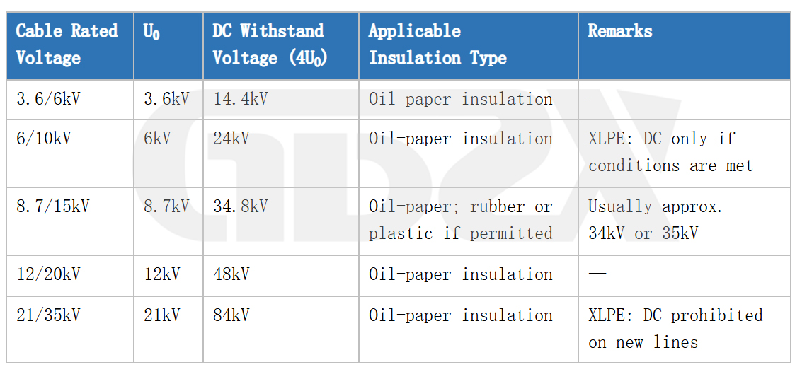
Note: For 35 kV XLPE-insulated cables, DC testing must not be used for commissioning tests in new installations. AC withstand testing using a series-resonant system should be adopted.
6.3 Comparison of Test Duration Standards
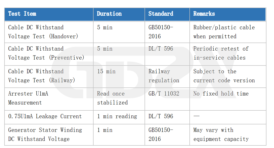
Common Field Practice Regarding the “1-Minute” Test Duration: The 1-minute duration applies only to specific test items, such as DC withstand testing of generator stator windings, as specified in GB 50150-2016. For DC withstand testing of cables, the standard test duration specified in the latest version of GB 50150-2016 is 15 minutes. This issue is widespread in the industry and is one of the common causes of discrepancies between actual field operations and test reports.


