


NEWSnews
DC High-Voltage Testing: Field Operation, Safety, Selection & Troubleshooting
七、Field Operating Procedures
7.1 Wiring Sequence — A Safety Logic That Must Not Be Reversed
The wiring sequence is governed by strict safety principles. It is not merely a matter of habit, but a fundamental rule for preventing electric shock accidents.
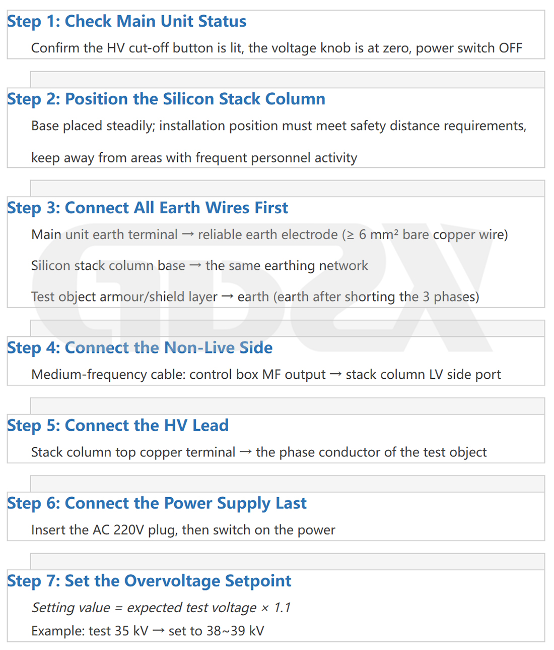
Why the Grounding Lead Must Be Connected First
The copper terminal at the top of the high-voltage silicon stack and the high-voltage lead can accumulate significant induced voltage through electrostatic induction when located near energized equipment or in a high-voltage field. If grounding is not connected first, the accumulated induced charge may discharge abruptly when personnel touch these conductors, causing burns in minor cases and potentially fatal injury in severe cases.
Connecting the grounding lead first clamps all conductors to ground potential, thereby eliminating the hazard posed by induced voltage.
7.2 Voltage Rise Operation
Start-up: Press the High-Voltage ON button (enabled only when the knob is at the zero position). After confirming that the High-Voltage ON indicator is illuminated, begin turning the voltage adjustment knob.
Voltage Rise Rate
1.Normal Test Specimens: Recommended at 1–2 kV/s, not exceeding 3 kV/s.
2.Test Specimens of Unknown Condition or Aged Specimens: Recommended at ≤0.5 kV/s, with pauses at each multiple of U₀ to observe the test specimen condition.3. 3.Lon Cables (500 m or Longer): Due to the high charging current, a voltage rise rate of 0.5 kV/s is recommended to avoid triggering overcurrent protection by charging-current peaks.
Real-Time Monitoring: Throughout the entire voltage rise process, simultaneously monitor the voltage and current meters. During normal charging of a capacitive load (cable), the current will temporarily increase as the voltage rises and then stabilize. If the current is found to increase continuously and significantly during voltage rise (rather than as a charging transient), immediately stop increasing the voltage and determine whether the test specimen has an insulation defect.
Step-by-Step Recording: As required by the applicable procedures, pause for 1 minute at each U₀ multiple (1U₀, 2U₀, 3U₀, and 4U₀) and record the leakage current. A nonlinear acceleration in the current increase between successive voltage levels is a diagnostic indication of insulation deterioration.
Why the Voltage Rise Rate Should Not Be Too High: For test specimens with insulation defects, a slow voltage rise allows abnormal leakage current to be detected at a lower voltage, providing early warning to the operator. An excessively rapid voltage rise may directly drive the voltage beyond the breakdown threshold, resulting in dielectric breakdown and damage to the test specimen.
Handling Trips During Testing of Long Cables: If overcurrent protection is frequently triggered during voltage rise, the usual cause is that the charging current exceeds the equipment's rated current. Recommended actions: ① reduce the voltage rise rate to below 0.3 kV/s; ② if repeated attempts are still unsuccessful, the equipment's rated current is insufficient and a higher-current model should be used. For cables longer than 3 km, calculate the required charging current in advance and configure equipment rated at 5 mA or higher.
7.3 Phase-by-Phase Testing of Three-Phase Cables
Three-core cables shall be tested phase by phase. Applying test voltage to all three phases simultaneously is prohibited.
Wiring for Each Test: Connect the conductor of the phase under test to the high-voltage terminal. Short-circuit the other two phase conductors together with the armor/shielding layer and connect them to ground. This wiring applies phase-to-ground voltage and provides a combined test of the main insulation (phase-to-ground) and interphase insulation (through the ground return path).
Treatment of Both Cable Ends: At the test end (high-voltage side), make the connections according to the normal test configuration. At the non-test end (remote end), short-circuit all three phase conductors together and connect them to ground; do not leave them floating. The induced voltage at a floating end of a long cable can reach hazardous levels and may also interfere with leakage-current measurement accuracy.
Regarding Whether Both Ends Need to Be Tested Separately: For cables with intermediate joints, testing is generally performed section by section, with both sides of each joint connected according to the above method. For a continuous cable without joints, test voltage may be applied from either end, provided that the other end is properly short-circuited and grounded.
7.4 Discharge Operation — The Stage Most Prone to Safety Accidents
Capacitive test specimens such as cables can store considerable electrical energy under high voltage. For example, consider a 400 m, 10 kV three-core cable with a capacitance of approximately 1.5 μF tested at 35 kV:
E = 1/2 × C × U² = 1/2 × 1.5 × 10⁻⁶ × (35,000)² ≈ 919 J
This is comparable to the kinetic energy of a handgun bullet. After the power supply is switched off, the stored energy does not dissipate automatically and remains essentially stored in the equivalent capacitance of the cable. Directly touching a high-voltage lead or test specimen with residual charge can cause fatal injury.
Correct Discharge Sequence:
① Slowly turn the voltage adjustment knob counterclockwise to the zero position.
② Press the High-Voltage OFF button (disconnect the high-voltage output first).
③ Turn OFF the power switch.
④ Wait 2–3 minutes to allow the capacitor to discharge naturally through the internal resistance.
⑤ Take the discharge rod and confirm that its grounding lead is securely grounded.
⑥ Touch the metal end of the discharge rod to the terminal at the top of the silicon stack and maintain contact for several seconds to discharge to ground.
⑦ Then touch the discharge rod to the high-voltage terminal of the test specimen (at the alligator clip) and maintain contact for several seconds.
⑧ Repeat Step ⑦ two to three times.
⑨ Use a tested high-voltage voltage detector to verify that no residual voltage remains.
⑩ Only after the voltage has been confirmed to be zero may the high-voltage leads and test specimen be touched.
Reliable Voltage Verification Method: Use a high-voltage voltage detector rated for the test voltage level. The detector should be inspected regularly and used only within its inspection validity period. If a high-voltage voltage detector is unavailable, use an insulated tool to temporarily short-circuit the high-voltage terminal to ground, then use a multimeter in DC voltage mode to measure the voltage to ground at the short-circuit point. A zero reading is required before the equipment can be considered fully discharged. Do not assume the equipment is safe simply because a sufficient amount of time has elapsed. The insulation resistance of different cables can vary significantly, and the natural discharge time may be much longer than empirical estimates.
7.5 Applications of Current-Limiting Resistors
A current-limiting resistor (typically 100 kΩ–1 MΩ) is connected in series between the high-voltage output of the silicon stack and the test specimen. Its function varies depending on the type of test specimen:
For Capacitive Loads (Cables, Capacitors): During the initial voltage-rise stage, the charging-current peak of a cable can be very high. The transient current may greatly exceed the rated surge current of the rectifier diodes, potentially causing component damage. Connecting a current-limiting resistor in series can effectively limit the charging-current peak and extend the service life of the silicon stack.
For Resistive Loads (Generator Windings, Transformer Insulation): The leakage current of these loads is inherently small, so a current-limiting resistor is generally not required for protection and may be omitted.
For Surge Arrester Testing: Whether a current-limiting resistor is required depends on the manufacturer's instructions and applicable test procedures. The resistor causes a voltage drop across its terminals (ΔU = I × R), so the actual voltage applied to the surge arrester is slightly lower than the value displayed by the main unit. Where precise U1mA measurement is required, this voltage drop should be taken into account for correction.
Heating of the Current-Limiting Resistor: Heating indicates that a relatively large current is flowing through the resistor (P = I²R). This commonly occurs in two situations: (1) the voltage rise rate is too high when testing a long cable, resulting in excessive charging current; or (2) the test specimen has an insulation defect, resulting in abnormally high leakage current. If significant heating occurs, reduce the voltage rise rate and check the insulation condition of the test specimen. Do not forcibly continue increasing the voltage.
八、Comparison with Series Resonance and VLF Test Systems
This is one of the most critical factors in selecting high-voltage test equipment and remains one of the most debated topics in the industry.
8.1 Fundamental Differences Among the Three Test Systems
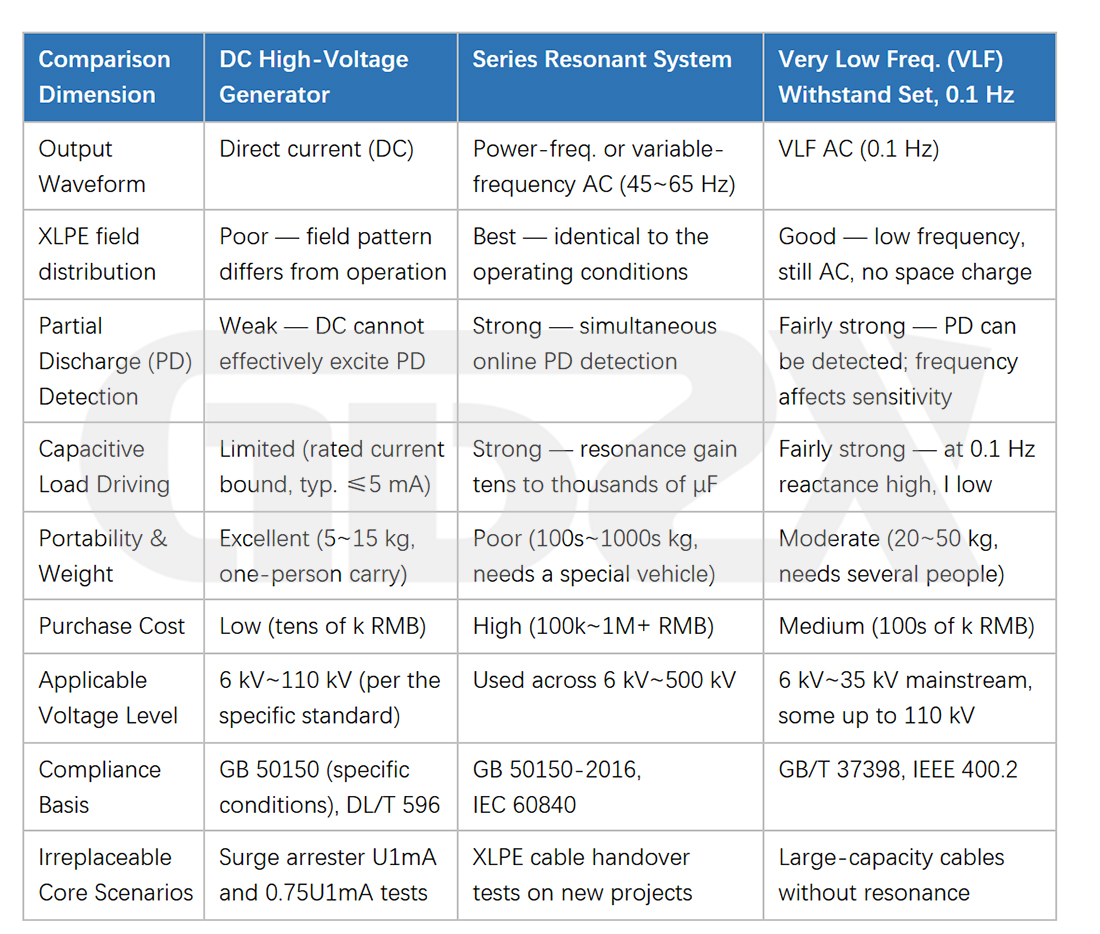
8.2 Application Logic of the Three Test Systems
In one sentence, the relationship among the three can be summarized as follows: for XLPE cable insulation testing, the suitability ranking is series resonance > VLF > DC; however, for dedicated surge arrester testing, DC is the conventional choice.
This ranking does not represent an absolute hierarchy of superiority. It reflects suitability for specific tasks. Different test scenarios require different tools:
1.Commissioning Tests for New XLPE Cables: Series-resonant AC withstand testing is the preferred method, in line with the current direction of applicable standards.
2.Large-Capacity or Aged Cables, or Where Resonance Conditions Cannot Be Met: Very-low-frequency (VLF) testing is an alternative option.
3.Oil-Paper-Insulated Cables: DC withstand testing remains a compliant and effective method.
4.Preventive Testing of All Zinc Oxide (ZnO) Surge Arresters: DC testing is required; AC test systems cannot replace it.
8.3 Regional Differences in Standards Must Not Be Overlooked
National standards provide the baseline requirements, but the implementation procedures of local asset owners are often more stringent. Some provincial power grid companies impose additional restrictions on test methods, for example:
1.Some provinces do not recognize the very-low-frequency (VLF) test method and accept only series-resonant AC withstand testing.
2.Some provinces impose explicit restrictions on the types of cable insulation for which the DC method may be used in preventive testing.
3.The railway industry has its own independent equipment acceptance procedures, which differ from those of the power industry in some applications.
Therefore, before determining the test method and purchasing equipment, both the applicable national standards and the specific implementation requirements of the owner or supervising party must be verified. Decisions should not be made based solely on the provisions of national standards.
九、Common Faults and On-Site Troubleshooting
Q1: Overcurrent Protection Trips at a Certain Voltage and the Target Voltage Cannot Be Reached
Cause A: The Test Specimen Has High Capacitance, and the Charging Current Exceeds the Equipment's Rated Current
This is the most common situation when testing long cables. The charging current can be estimated as:
I (mA) = C (μF) × dU/dt (kV/s).
For a 500 m cable with a capacitance of approximately 2 μF, the charging current is about 2 mA at a voltage rise rate of 1 kV/s. If the equipment is rated at 2 mA, the protection may be triggered by the charging-current transient.
Solution: Reduce the voltage rise rate to 0.3–0.5 kV/s, or replace the equipment with a model having a higher rated current (3 mA/5 mA).
Cause B: The Test Specimen Has an Insulation Defect, Resulting in Excessive Leakage Current
If the leakage current itself triggers the overcurrent protection, this is a test result indicating an insulation problem in the test specimen. Record the voltage at which the protection trips and issue a nonconformance report.
Cause C: Improper Overvoltage/Overcurrent Protection Setting
Check whether the setting dial is correctly adjusted. The protection setting voltage should be set to 1.1 times the test voltage, rather than to a lower setting.
Q2: The Main Unit Displays Voltage, but the Actual Voltage at the Test Specimen Is Low or Zero
1.Poo contact between the high-voltage lead and the test specimen (insufficient alligator-clip contact area, or oxidation, oil, or contamination on the specimen terminal).
2.Damage to the outer shielding layer of the high-voltage lead, causing high-voltage leakage to ground.
3.Moisture on the outer surface of the silicon stack, causing surface leakage.
4.Improper insulation wrapping at the connection point, creating a surface leakage path.
Q3: Output Voltage Is Unstable and Fluctuates
1.Unstble Power Supply: This is particularly common when a generator is used for outdoor operation. Install a voltage stabilizer or use a higher-capacity generator with stable output.
2.Aged or Faulty Inverter Control Board: The equipment should be returned to the manufacturer for inspection.
3.Excessive Ambient Temperature Causing Component Thermal Drift: Ensure adequate heat dissipation for the equipment.
Q4: The High-Voltage ON Button Is Ineffective and High-Voltage Output Cannot Be Enabled
1.The Voltage Adjustment Knob Is Not at Zero, Triggering Zero-Position Protection: Turn the knob fully counterclockwise to the zero position and try again.
2.The Intermediate-Frequency Output Wiring Is Incomplete (Some Models Have No-Load Protection): Check the wiring on the low-voltage side of the silicon stack.
3.The Main Fuse Has Blown: Open the enclosure, inspect the fuse, and replace it with one of the same specification.
Q5: Ammeter Readings Fluctuate Abnormally and Irregularly
1. The Conductors at the Remote End (Non-Test End) of the Test Specimen Are Floating and Ungrounded, Resulting in External Electromagnetic Interference: Short-circuit the three phases at the remote end and connect them to ground.
2. Poor Grounding of the Measurement Circuit, Introducing Stray Current: Check the connection quality of the grounding circuit.
3. Interference from High-Power Electrical Equipment Nearby: Change the testing time or move away from the interference source.
Q6: No Significant Voltage Response at the Remote End During Voltage Rise on Extra-Long Cables (Over 1 km)
This is a combined effect of insufficient charging current and distributed capacitance, which can occur when the equipment's rated current is too low. For extra-long cables, the required charging current should be calculated before purchasing the equipment, and a unit with sufficient rated current (5 mA or higher) should be selected. The voltage rise rate should also be strictly controlled.
Q7: Insulation Performance Degrades After Outdoor Use, Preventing the Test Voltage from Reaching the Rated Level
1.Moisture on the Outer Surface of the Silicon Stack: Wipe the surface clean with a clean nonwoven cloth. If conditions permit, use a heat gun at low temperature to dry the surface. Retry only after the surface is completely dry.
2.Moisture Absorption During Long-Term Storage: Perform thorough drying of the entire high-voltage silicon stack.
3.Aging of Insulation Materials Resulting in Microcracks: This is more common in products that have been in service for many years. Return the equipment to the manufacturer for inspection and repair or replace the affected components.


