


NEWSnews
DC High-Voltage Generator: Selection, Acceptance & FAQs
十、Procurement Selection Guide
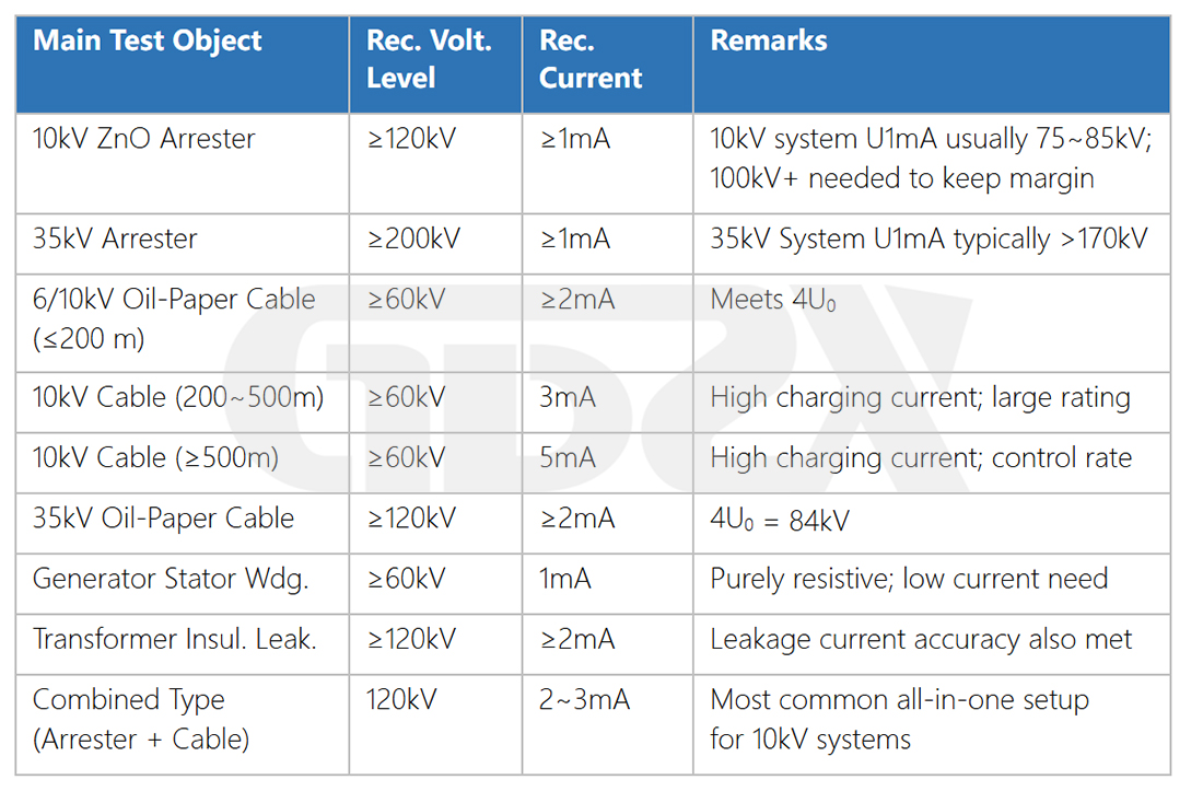
10.1 Select Specifications by Test Object
10.2 Current Rating Selection Calculation
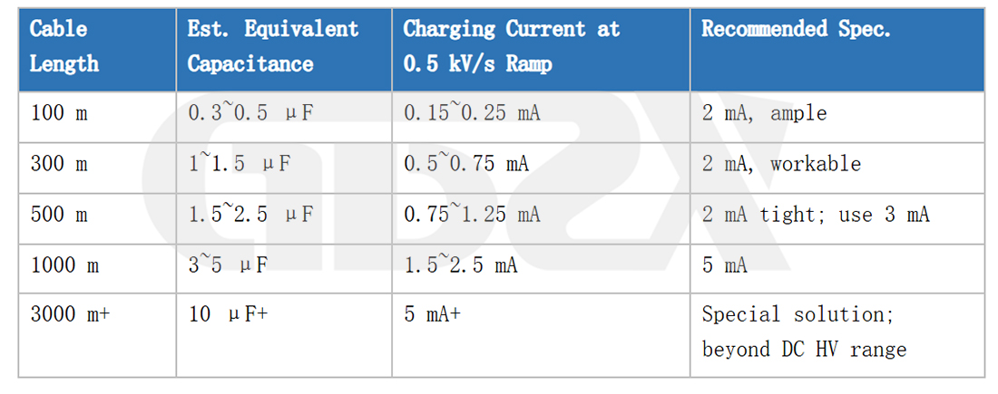
Estimated cable charging current formula:
I(mA)= C(μF)× dU/dt(kV/s)
10.3 Selection Logic: Standard vs. Intelligent Models
When to Choose the Standard Model:
1.Operators are experienced and routinely engaged in high-voltage testing.
2.Frequent on-site relocation makes weight and portability important.
3.Budget is limited, with no mandatory requirement for automatic data recording.
4.Primarily used for preventive testing and routine maintenance, with relatively flexible report-format requirements.
When to Choose the Intelligent Model:
1.Formal project handover testing, with strict report-format requirements from the client or supervisor.
2.Digital data archiving is required to meet quality management system audit requirements.
3.High-volume arrester testing, with specific requirements for U1mA measurement accuracy (ripple ≤0.2%).
4.The organization is undergoing digital transformation and implementing a unified equipment data management platform.
5.Frequent operator turnover, where the wiring diagram inside the case lid can reduce the risk of incorrect operation.
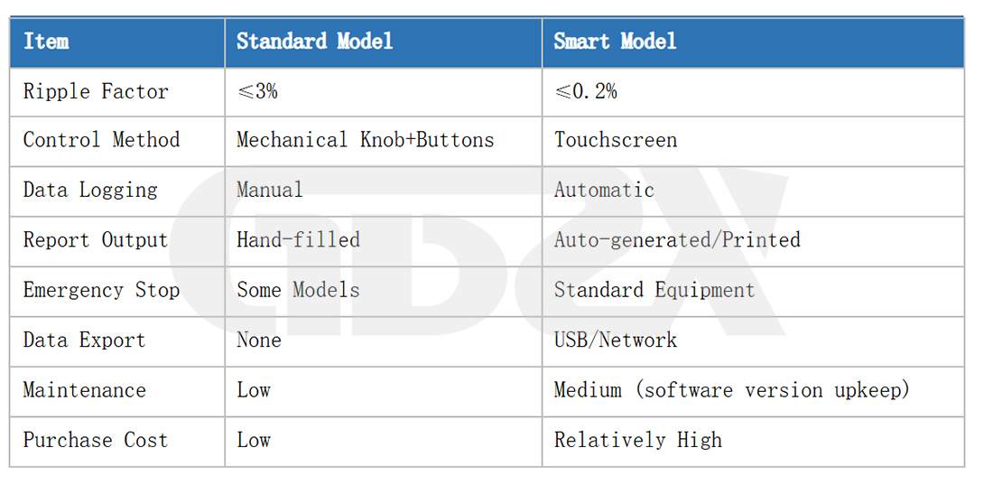
Key Differences Between the Two Product Types:
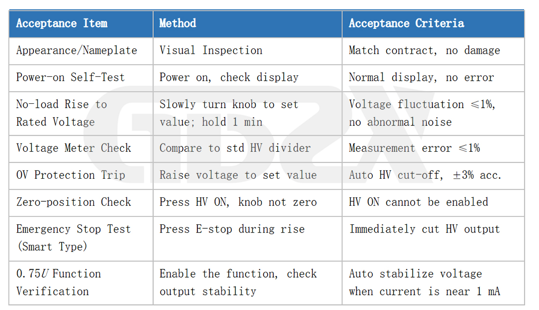
10.4 Acceptance Testing Upon Delivery
After receiving the equipment, the following acceptance tests are recommended. Any issues identified should be addressed within the warranty period:
十一、Frequently Asked Questions (FAQs)
The following questions reflect common concerns raised by front-line high-voltage testing personnel, highlighting some of the most common knowledge gaps and operational questions in this field.
Q: Can XLPE cables be tested using DC withstand voltage testing?
Yes, but only under specific conditions; it is not universally prohibited. GB 50150-2016 retains a provision allowing DC testing for XLPE cables rated 18/30 kV and below when AC withstand testing is not feasible. However, for formal handover testing of new projects, AC withstand voltage testing is preferred. DC testing is prohibited for XLPE cables rated 110 kV and above. Whether DC testing is permitted should also be verified against the applicable local owner's testing procedures, as some provinces have stricter requirements than the national standard.
Q: What DC test voltage should be applied to a 10 kV cable?
It depends on the rated voltage marked on the cable nameplate. For a 6/10 kV cable (U₀ = 6 kV), the DC withstand test voltage is 4U₀ = 24 kV. For an 8.7/15 kV cable (U₀ = 8.7 kV), the DC withstand test voltage is approximately 34.8 kV; in practice, 34 kV or 35 kV is commonly used. Both cable types are used in 10 kV distribution systems, but their test voltages differ significantly. Always check the cable nameplate before testing.
Q: Should the test duration be 1 minute, 5 minutes, or 15 minutes?
GB 50150-2016 specifies a standard test duration of 5 minutes. Certain railway industry procedures require 15 minutes. One minute is a common field practice for rapid assessment, but it does not meet the requirements of a formal standard. When issuing an official test report, the duration must be recorded according to the specific applicable procedure and its version. The reported duration must be consistent with the actual test procedure. This is an important issue affecting the compliance of test reports and is a common practical problem in the industry.
Q: What leakage current is considered acceptable?
DL/T 596 specifies ≤50 μA, but this should not be used as the sole criterion. Year-on-year trends should also be considered. For example, if the leakage current increases from 10 μA last year to 45 μA this year, it remains below 50 μA but should still be regarded as abnormal. The year-on-year rate of increase should also be monitored. An increase of more than 50% or an absolute value approaching the limit warrants attention.
Q: Can a 500 m cable be tested with a DC high-voltage generator? What current rating is required?
Technically, yes, provided that the current rating is sufficient. A 500 m, 10 kV three-core cable typically has a capacitance of approximately 1.5–2.5 μF. At a voltage rise rate of 0.5 kV/s, the charging current is approximately 0.75–1.25 mA. A 2 mA unit is recommended, with the voltage rise rate controlled at or below 0.5 kV/s. If a higher normal rise rate is required, a 3 mA or 5 mA unit provides greater margin and helps prevent frequent overcurrent protection trips.
Q: How can I confirm that the test object has been safely discharged and can be touched?
After repeatedly short-circuiting the test object with a discharge rod, use a regularly inspected high-voltage detector to verify that no voltage remains. The test object may only be touched after the voltage is confirmed to be zero. If a high-voltage detector is unavailable, an insulated tool may be used to short the high-voltage terminal to ground, followed by measurement of the voltage between the shorted point and ground using a multimeter in DC voltage mode. A zero reading can be used as an indication of a safe condition. Do not rely solely on waiting time, because insulation resistance varies among cables and the natural discharge time cannot be predicted.
Q: Is a current-limiting resistor mandatory? Will it affect measurement accuracy?
For capacitive loads such as cables and capacitors, a current-limiting resistor is recommended to protect the rectifier components in the high-voltage silicon stack. After the resistor is added, the milliammeter reading, which represents the series-circuit current, remains unchanged. However, the actual voltage applied to the high-voltage side will be slightly lower than the value indicated by the main unit due to the voltage drop across the resistor (voltage drop = I × R). At typical test-current levels, from μA to low-mA ranges, and with commonly used resistance values below 1 MΩ, the voltage drop is generally within an acceptable range. If the current is relatively high or strict accuracy is required, the actual applied voltage should be corrected. For arrester testing, whether a resistor should be installed and how the correction should be performed should follow the applicable testing procedure and equipment manufacturer's instructions.
Q: What generator power rating is required when using a generator as the power source?
During no-load or light-load testing with very low leakage current, the DC high-voltage generator itself typically consumes approximately 100–200 W, so a 2 kW generator is generally sufficient. For large-capacitance loads such as long cables, however, the transient power during charging can reach approximately 1–3 kW. A generator rated at 5 kW or above is therefore recommended to ensure stable power supply. An unstable generator output voltage can increase output ripple from the DC high-voltage generator and affect measurement accuracy. A voltage stabilizer may be added when necessary.
Q: Should a three-phase cable be tested one phase at a time, or can all three phases be tested simultaneously?
Each phase must be tested separately; simultaneous application of high voltage to all three phases is not permitted. The standard procedure is to connect the phase under test to the high-voltage terminal while shorting the other two phases and the armor/shield layer together and grounding them. This applies the full phase-to-ground voltage while testing both the main insulation and inter-phase insulation. Simultaneous high-voltage application to all three phases does not comply with testing procedures and cannot identify which phase has a problem.
Q: Can a DC high-voltage generator actually detect cable faults? Some people say its effectiveness is limited.
Within its applicable scope, DC withstand voltage testing can effectively detect serious insulation defects. When a damaged insulation point produces abnormally increased leakage current under high voltage, or even breakdown discharge (commonly referred to as flashover), the fault can be directly detected. For oil-paper-insulated cables and severely damaged XLPE cables, DC withstand testing can provide reliable detection. However, for early-stage insulation defects in XLPE cables, such as small partial-discharge sites, the detection capability of DC testing is significantly lower than that of AC withstand testing. This is also a fundamental reason why standards have shifted toward AC withstand testing. A “pass” result from a DC high-voltage test on an XLPE cable should not be interpreted as proof that the cable insulation is healthy.
Appendix: Overview of Relevant Standards
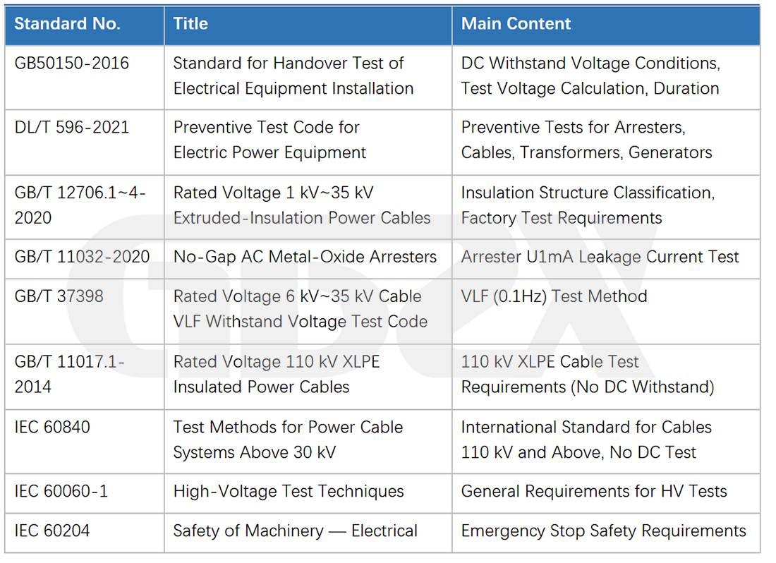
This article has been compiled based on current national standards and industry regulations, with reference to extensive practical experience from front-line high-voltage testing personnel. It is provided for technical reference only. Specific test methods shall be based on the applicable version of the relevant procedures. In the event of a standards update, the latest officially issued version shall prevail.


