


NEWSnews
Power-Frequency Withstand: Procurement & Selection Guide
十、Common Procurement Concerns Identified from Frequently Asked Questions
Based on common questions raised during procurement discussions, buyers’ biggest concerns before signing a contract are often not simply whether the equipment can achieve the required test voltage, but whether it can be delivered, operated, and accepted smoothly after purchase. The following questions are therefore worth addressing in advance in the technical clarification or procurement Q&A.
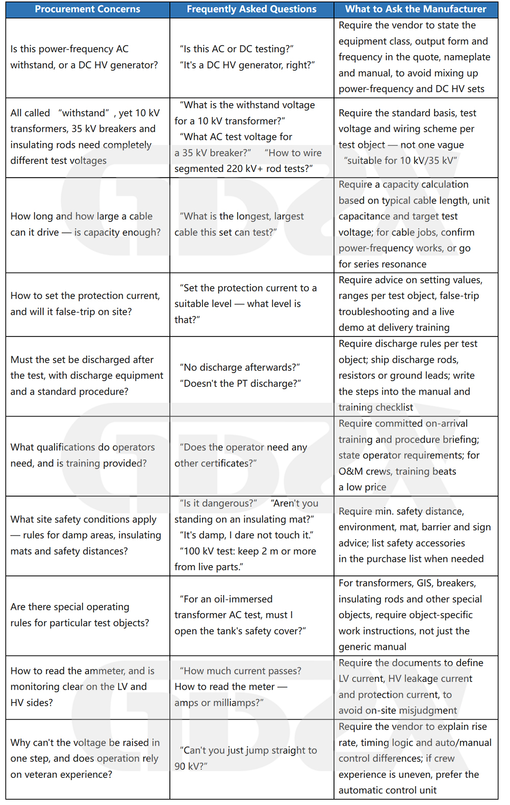
In procurement terms, these concerns can be distilled into four key points: the equipment category must be clearly defined, the applicable test-object boundaries must be clear, the capacity must be properly matched, and delivery and training requirements must be clearly specified. If the manufacturer provides vague answers to these questions, the risk of problems during implementation can increase significantly, even if the main unit’s specifications look impressive on paper.
十一、Specification Selection & Calculation Examples
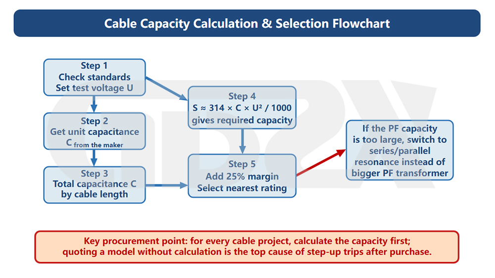
Figure: Cable Capacity Calculation and Equipment Selection Flowchart
11.2 How to Determine the High-Voltage Rating
Step 1: Refer to the relevant section of GB 50150-2016 for the test object and confirm the specified withstand test voltage.
(This value must be taken from the applicable standard clause and must not be estimated independently.)
Step 2: Add a 20%–30% margin to the test voltage to determine the equipment’s rated high-voltage output.
Step 3: Select the nearest available rating in the product series that is ≥ the calculated value.
Example:
Test object: 10 kV switchgear
Standard reference: Chapter 6 of GB 50150-2016; withstand test voltage ≈ 34 kV
With 25% margin: 34 × 1.25 = 42.5 kV
Selection: 50 kV rating (nearest available rating in the product series)
11.3 How to Calculate Required Capacity (for Capacitive Test Objects)
Capacitive test objects, such as cables and bushings, generate capacitive current when energized. This is the primary source of the load on the test transformer.
Core formula:
S = 2π × f × C × U²
Where:
S — Required capacity (kVA)
f — 50 Hz
C — Test-object capacitance (F)
U — Test voltage (V)
Using common units, with C in μF and U in kV:
S (kVA) ≈ 314 × C (μF) × U² (kV²) ÷ 1000
11.4 Complete Cable Capacity Calculation Example
Given:
Cable length: L (m)
Capacitance per unit length: C₀ (μF/km) — obtain from the cable manufacturer or product technical data
Test voltage: U (kV) — refer to the applicable clause of GB 50150-2016
Calculation steps:
① Total capacitance: C = C₀ × L / 1000 (μF)
② Required capacity: S = 314 × C × U² / 1000 (kVA)
③ Add 25% margin: S_selection = S × 1.25 (kVA)
④ Select the nearest available capacity rating in the product series that is ≥ S_selection
Example: L = 200 m, C₀ = 0.25 μF/km, U = 34 kV
① C = 0.25 × 200 / 1000 = 0.05 μF
② S = 314 × 0.05 × 34² / 1000 ≈ 18.1 kVA
③ S_selection = 18.1 × 1.25 ≈ 22.7 kVA
④ Select YDQW 30/50 (30 kVA, 50 kV) from the YDQW series
Note: The C₀ value must be obtained from the cable manufacturer’s technical data. It varies significantly among different cable types and models and must not be replaced with a generic estimated value.
11.5 Long-Cable Assessment: When Is Power-Frequency Testing Not Feasible?
When the calculated required capacity exceeds the maximum available capacity of the existing equipment, a power-frequency withstand test solution is not feasible. In this case, a resonant test system should be used instead of continuously increasing the capacity of the power-frequency test transformer.
Estimated excitation power for the resonant system:
S_excitation = S_power-frequency / Q
Where:
Q — Resonance quality factor, typically 30–100 (the specific value should be provided by the resonant test system manufacturer)
Example:
Power-frequency capacity required: 90 kVA
Q = 50
S_excitation = 90 / 50 = 1.8 kVA
11.6 Capacity Assessment for Non-Capacitive Test Objects
For test objects such as switchgear, circuit breakers, transformers, motors, and busbars, the capacitance is typically at the pF level, so the capacitive load is generally negligible.
The capacity selection principle for these test objects is therefore: select the smallest available capacity rating in the product series, with the voltage rating being the primary selection criterion.
Typically, 5 kVA can cover non-capacitive equipment in 10 kV systems, while 10 kVA can cover 35 kV systems. However, actual selection must still be verified against the equipment parameters and applicable standards; these values must not be applied mechanically.
11.7 YDQW Series Specification Quick Reference
Data source: Technical documentation for the YDQW Series Inflatable Partial-Discharge-Free Test Transformers
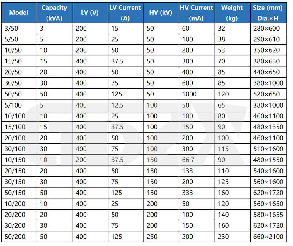
Accuracy: Voltage ≤1.5% ±1 digit (F.S.); Current ≤1.5% ±1 digit (F.S.); Timing Range: 0–9999 s.
十二、Conclusion: How Procurement Teams Should Make the Right Decision
This article can be distilled into five key actions:
First: Check the standard before discussing specifications.
The test voltage should not be estimated by intuition. It must be determined by referring to the applicable section of GB 50150-2016. Until this value is confirmed, do not start discussing the required high-voltage rating.
Second: For cable testing, calculate the required capacity.
Use the formula above, input the cable length and capacitance per unit length, calculate the required capacity, and then select the equipment. Specifying a model without performing the calculation significantly increases the risk of tripping during testing.
Third: Let the application determine the equipment configuration and insulation medium.
For fixed installations, oil-immersed units and control consoles are common. For mobile testing, inflatable/gas-insulated units and control boxes are more suitable. Whether partial-discharge testing is required is another key consideration; for such applications, a gas-insulated partial-discharge-free configuration is generally required. These three considerations cover most procurement scenarios.
Fourth: The value of an automatic system goes beyond convenience.
Stable and repeatable voltage ramping, standardized test reports, and reduced human error all contribute to compliance, not merely ease of operation. For projects requiring reports to be submitted to the client or subject to inspection and supervision, an automatic system is a reasonable choice.
Fifth: Include compliance requirements in the contract.
Valid metrology certificates (CMA, within the validity period), three protection functions that can be verified on site, and complete accompanying documentation are not optional advantages—they should be basic contractual requirements. Check each item during acceptance, and do not release non-compliant equipment.
Once these five steps are completed, the equipment can be properly selected, correctly used, and kept compliant, with procurement responsibilities clearly defined and project risks minimized.
Reference Standards
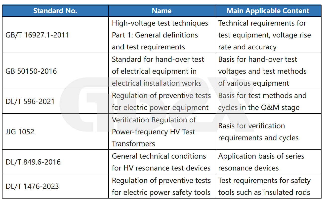
⚠️ The standard versions listed above are the reference versions used when this article was prepared. For actual projects, always refer to the latest valid versions in force. Before procurement, it is recommended to verify whether any of the applicable standards have been updated or superseded.
Product parameter source: YDZ / YDQW / GTB Series product technical documentation. Specific parameters shall be subject to the actual product nameplate and applicable valid standards. This article does not constitute a technical basis for a procurement contract.


