


NEWSnews
Power-Frequency Withstand Test: Principles & Equipment
Chapter 01
01 | What Is a Power-Frequency Withstand Test? |
1.1 Definition and Fundamentals
Power Frequency Withstand Voltage Test (Power Frequency Withstand Voltage Test) is a withstand test classified as a destructive high-voltage test, in which AC high voltage at the power frequency (50 Hz or 60 Hz) and with an amplitude higher than the rated operating voltage is applied to the electrical equipment under test for a specified duration, in order to assess whether the equipment insulation can maintain its integrity under overvoltage conditions. This test is widely used in various scenarios, including factory inspection, commissioning acceptance, and preventive testing, and is not limited to the "acceptance" stage.
The term "destructive" does not mean that the test is intended to damage the equipment. Rather, it means that the test voltage is sufficient to expose potential insulation defects. If the insulation has hidden defects such as air gaps, impurities, moisture, or mechanical damage, breakdown or intensified partial discharge may occur under the specified overvoltage, thereby identifying such defects. If the insulation is qualified, the equipment can withstand and pass the test, indicating that it meets the conditions for safe commissioning and operation.
2.DC Withstand Voltage Test**: A DC high voltage is applied, and this test is commonly used for rotating machines, cables, and other equipment. It has a different focus from the power-frequency test and cannot simply be used interchangeably. 3.Partial Discharge Measurement**: A more precise non-destructive testing method that is used in conjunction with power-frequency withstand testing to assess the internal discharge condition of insulation. |
1.2 Why Must Power Frequency Be Used?
The operating frequency of the power system is 50 Hz (according to Chinese standards). The mechanisms of insulation aging, thermal breakdown, and partial discharge under an AC electric field are closely related to frequency. Therefore, using power-frequency voltage for testing ensures that the applied electrical stress is **consistent with the electrical stress experienced by the equipment during actual operation.
This is not merely a conventional practice, but is based on physical principles:
1.The dielectric loss tangent (tanδ)of insulating materials is frequency-dependent, and measurements at power frequency most accurately reflect actual operating losses.
2.Electric field distribution, space charge accumulation, and partial discharge inception voltage are all related to frequency.
3.Under a power-frequency alternating electric field, insulation defects such as air gaps and poor contacts experience polarity reversal during each half-cycle, making them more likely to reveal weaknesses caused by space-charge effects than under DC conditions.
4. As a basis for acceptance and arbitration , power-frequency withstand testing provides a repeatable and comparable testing standard. Power-frequency testing is therefore used as one of the primary methods for commissioning and acceptance tests in standards and regulations worldwide.
|
1.3 The Role of Power-Frequency Withstand Testing in the Overall Test System
Insulation tests for electrical equipment are generally divided into two major categories: factory tests (type tests) and field tests. Field tests are further divided into commissioning and acceptance tests (before newly installed equipment is put into operation) and preventive tests (periodic inspections during operation).
Power-frequency withstand testing has a clearly defined role in different testing scenarios: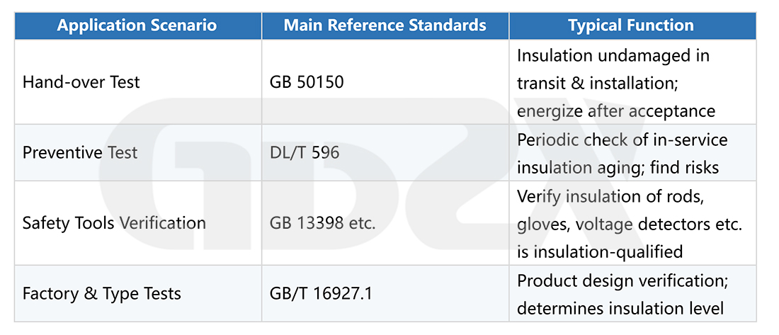
Chapter 02
02 | Principle and Test Circuit of Power-Frequency Withstand Testing |
2.1 Basic Circuit Principle
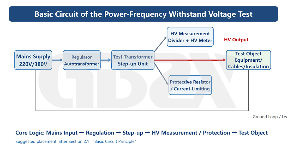
Figure 1. Schematic Diagram of the Basic Power-Frequency Withstand Test Circuit
The core of the power-frequency withstand test is to step up the power-frequency supply (220 V/380 V mains) to the required test voltage through a voltage regulator and a test transformer, and apply it across the equipment under test. The entire circuit consists of the following stages:
1. Power Input: Power-frequency mains supply of 220 V or 380 V, connected through a residual-current protection device and power switch.
2. Voltage Regulator (Autotransformer): Smoothly adjusts the input voltage from zero and controls the amplitude of the high-voltage output. It is the key component for gradually increasing the test voltage.
3. Test Transformer: Steps up the low-voltage output from the voltage regulator to the high test voltage required for the test (from several kV to several hundred kV). It is the core step-up device of the entire system.
4. Protective Resistor / Current-Limiting Resistor: Connected in series with the high-voltage circuit. When breakdown occurs in the equipment under test, it limits the short-circuit current, protects the test transformer, and reduces secondary damage to the equipment under test caused by the breakdown.
5. Overcurrent Protection Device: Automatically cuts off the power supply when the test current exceeds the preset value due to breakdown of the equipment under test or abnormal leakage current, preventing further damage.
6. High-Voltage Measuring Device: A voltage divider and voltmeter (or peak voltmeter) are used to monitor the actual high voltage applied to the equipment under test in real time.
7. Equipment Under Test: The equipment being tested, with one end connected to the high-voltage terminal and the other end grounded, or connected to a specific circuit according to the test requirements.
8. Leakage Current Measurement: An ammeter (microammeter or milliammeter) connected in series on the high-voltage ground side records the leakage current flowing through the insulation of the equipment under test.
2.2 Why Must the Test Voltage Be Increased Gradually Rather Than Applied All at Once?
This is one of the questions most frequently asked in field testing.
The reasons are multifaceted, and it is not simply a matter of "safety":
1.Equipment protection: Applying high voltage instantaneously can produce inrush current, imposing transient stress on both the test transformer windings and the equipment under test.
2.Observation of insulation behavior: Gradual voltage increase allows the operator to monitor changes in leakage current at each voltage stage. If an abnormal current surge occurs, the test can be stopped promptly to avoid unintended breakdown.
3.Standard requirements: Standardization Administration of China's current information identifies GB/T 16927.1-2011 as the current standard, while a revision based on IEC 60060-1:2025 is in progress. The exact voltage-rise procedure and rate should therefore be checked against the applicable test standard and equipment under test, rather than universally applying a fixed "3%/s" value.
4.Voltage regulator characteristics: Gradually increasing the voltage from zero helps maintain a controlled output and avoid excessive waveform distortion or transient effects associated with abrupt voltage application.
2.3 Relationship Between Capacity Requirements and Test-Object Capacitance
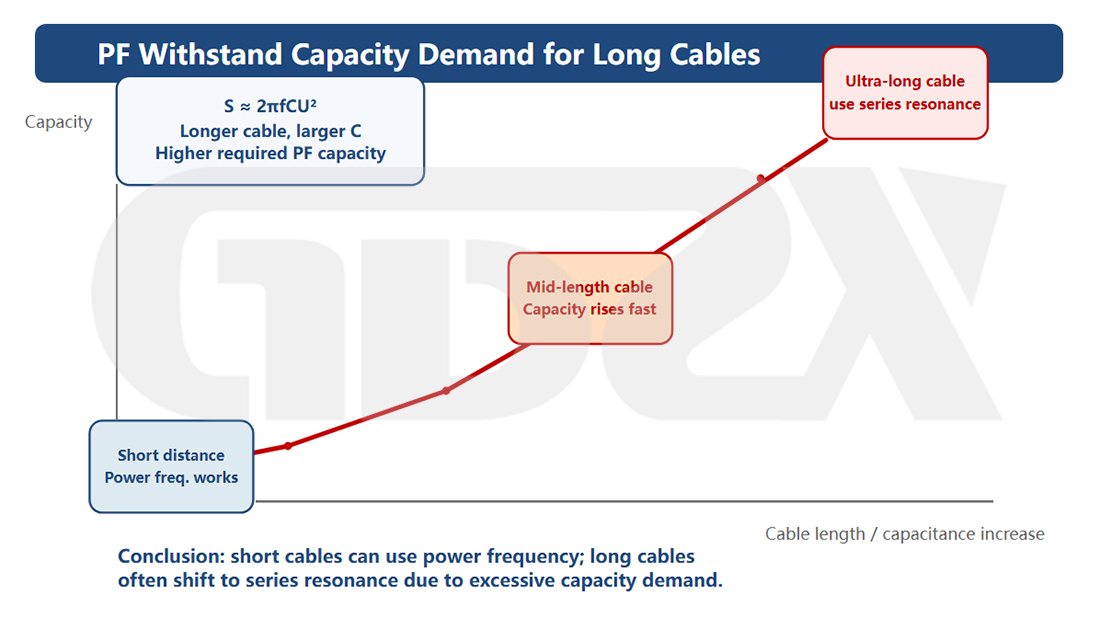
Figure 2. Schematic Diagram of Capacity Requirements for Power-Frequency Withstand Testing of Long Cables
The core challenge in power-frequency withstand testing is that the insulation of the equipment under test (especially cables, capacitors, and similar equipment) is equivalent to a purely capacitive load, while charging and discharging the capacitor with power-frequency AC requires reactive power.
Required Test Transformer Capacity (Approximate):
|
Example: If the test voltage is 10 kV and the capacitance of the cable under test is 2 μF, the required capacity is approximately 10² × 314 × 2 × 10⁻³ ≈ 62.8 kVA. This is why applying a power-frequency withstand test directly to long cables requires a very large equipment capacity and is often uneconomical in practice.
|
Chapter 03
03 | Composition and Classification of Power-Frequency Withstand Test Equipment |
3.1 Typical Equipment Components
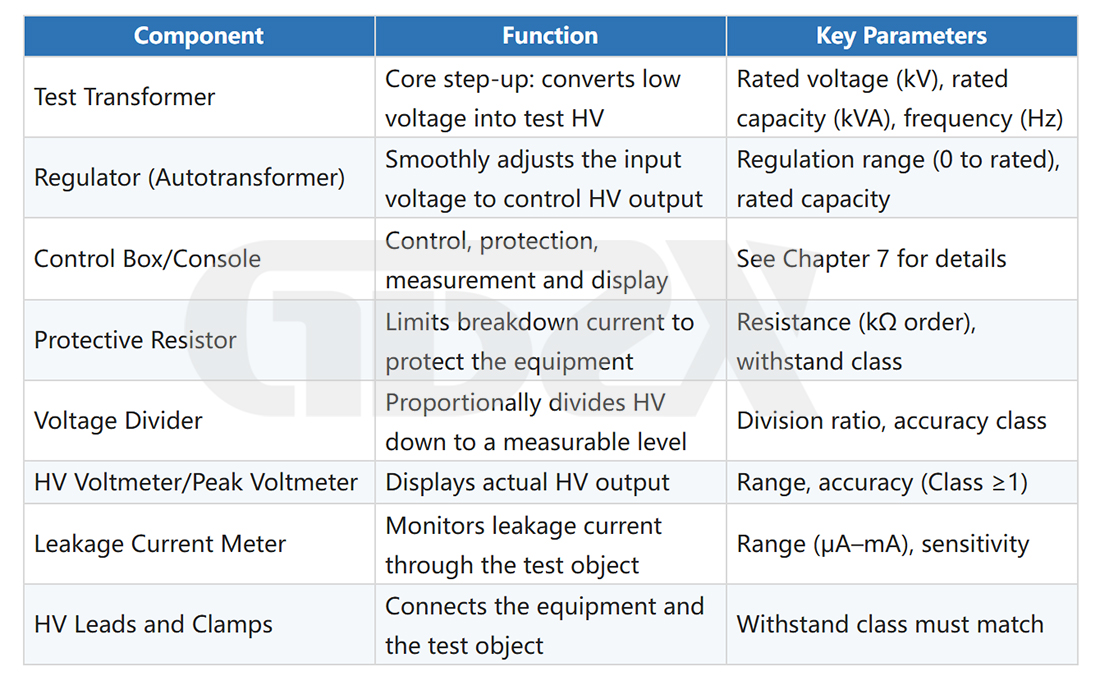
A complete power-frequency withstand test system typically consists of the following components:
3.2 Classification by Voltage Level
1.10 kV and below: Used for withstand testing of 0.4 kV–6 kV equipment and electrical safety tools.
2.50 kV–100 kV: The main range for commissioning and acceptance tests of equipment in 10 kV and 35 kV systems.
3.150 kV–300 kV: Used for certain equipment in 110 kV and 220 kV systems, subject to capacity limitations.
4.500 kV and above: Large-scale test station equipment, rarely used in the field and typically replaced by resonant test systems.
|
3.3 Single-Stage and Multi-Stage Cascaded Configurations
The output voltage of a single test transformer is limited. When a higher test voltage is required, multiple test transformers can be connected in cascade. The enclosure (core) of each transformer is insulated from ground, while the high-voltage windings are connected in series to multiply the output voltage. Two-stage and three-stage cascaded configurations are common. Theoretically, additional stages can be added, but insulation requirements and costs increase significantly.
The total capacity of a cascaded system is the sum of the capacities of the individual transformers, not their product. Therefore, high-capacitance equipment under test remains a challenge for cascaded systems, and capacity calculations are still required.
Cascade System Output Voltage (Reference): U_total = n × U_single (n = number of cascaded stages, assuming each stage has the same rated voltage) Total Rated Capacity of the Cascade System: S_total = n × S_single (The total capacity is the sum of the capacities of all stages, not their product.) Estimated Required Capacity for the Equipment Under Test (Capacitive Load): S_required (kVA) ≈ U² × 2πf × C × 10⁻³ Where: U = test voltage (kV, RMS); f = 50 Hz; C = capacitance of the equipment under test (μF). Example: U = 42 kV, C = 0.05 μF *(approximately a 200 m, 10 kV XLPE cable) → S_required ≈ 42² × 314 × 0.05 × 10⁻³ ≈ 27.7 kVA; a conventional 50 kVA test system can meet the requirement. |


