


NEWSnews
Power-Frequency Withstand Test: Standards, Test Methods & Transformer Comparison
Chapter 04
04 | Applicable Standards and Test Objects |
4.1 Current Applicable Standards
The standards involved in the power-frequency withstand voltage test fall into three levels: fundamental method standards, industry application codes, and metrological verification regulations. The three must not be mixed; they shall be applied separately according to the test object.
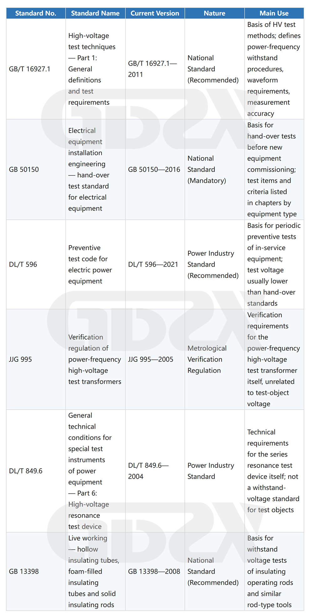
Important note: test voltages must not be applied across different objects. The same test set can be used to test different objects, but the test voltage for each type of test object must be looked up separately in its own corresponding standard clauses. For example, the hand-over test voltage of a 10 kV transformer, that of a 10 kV circuit breaker, and that of a 10 kV insulated rod differ from one another in both source and value, and must never be substituted for one another. |
4.2 Common Test Objects and Corresponding Standards (Examples)
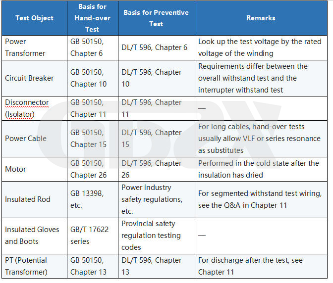
Principle for using this table: This table gives only the standard sources, not specific voltage values. The actual test voltage for each test object must be looked up in the currently valid version of the corresponding standard clauses, because values may change after standard revisions and differ among rated voltage classes.
Chapter 05
05 | Power-Frequency · VLF · Series Resonance — Comparison of Applicability Boundaries Under the Same Conditions |
This is the most critical decision in field selection: none of the three approaches is absolutely superior; each has its own applicability boundary. The following comparison is made under identical test objectives (insulation withstand acceptance), identical test objects (large-cross-section cables / switchgear / transformers), and identical project constraints (site work, budget, and standard requirements) rather than as a vague comparison of technical parameters.
5.1 Basic Characteristics of the Three Approaches
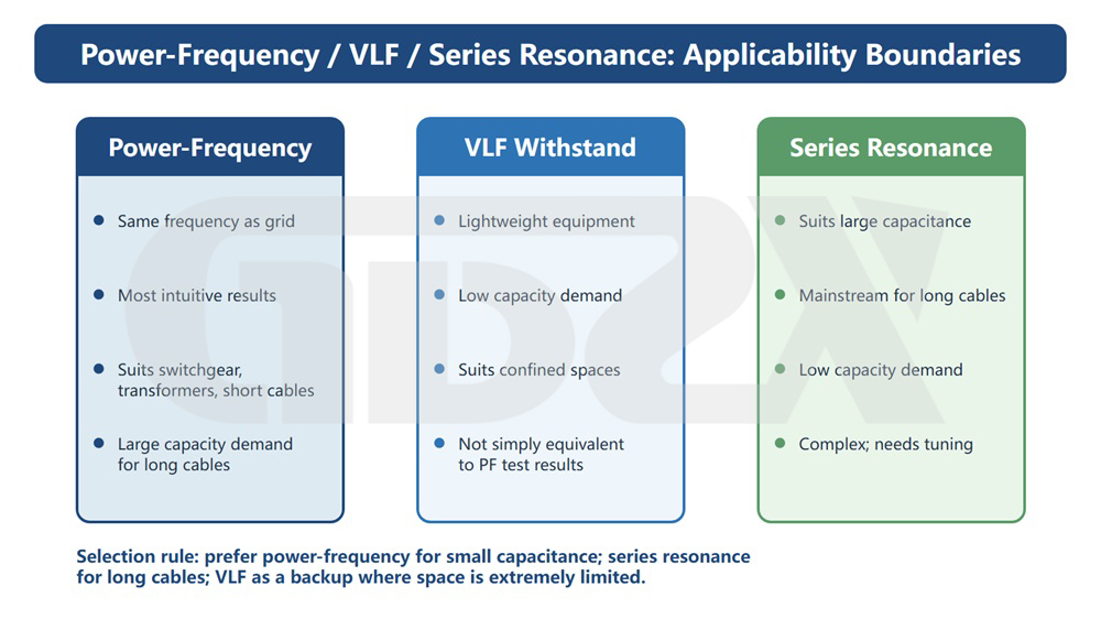
Figure 3 Applicability boundary comparison of power-frequency, VLF and series resonance
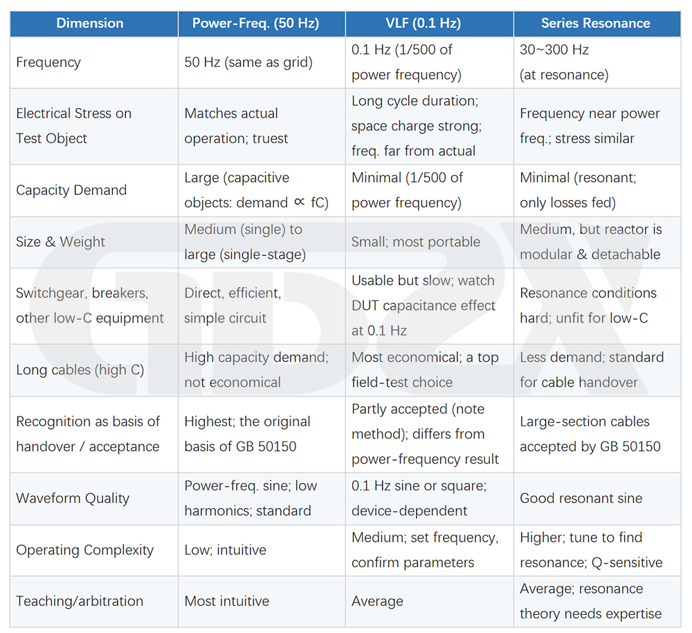
5.2 Interpretation of the Core Advantages of Power-Frequency Withstand
The reason why the power-frequency withstand test is designated as the reference method for the hand-over tests of most equipment is not merely “tradition”; there are clear physical and standards-based grounds:
• Frequency consistency: the electrical stress distribution, dielectric loss characteristics and partial discharge behavior at 50 Hz are fully consistent with the actual operating state of the equipment, so the results give the strongest prediction of operational reliability;
• Most efficient for small- and medium-capacitance objects: switchgear, circuit breakers, transformers, instrument transformers and safety tools usually have insulation capacitance at the nanofarad (nF) level; the capacity required at power frequency is not large, and one unit in the several-hundred-kVA class can cover the vast majority of field tests at 35 kV and below;
• The highest recognition in the standards: the hand-over test voltages in each chapter of GB 50150 are established on the power-frequency basis. When other methods are used, the standards usually note them as “replaceable”, whereas power frequency itself needs no such substitution note;
• Arbitration and dispute resolution: when test results are in dispute, the power-frequency withstand test is usually the final means of arbitration; results from other methods need re-verification at power frequency before a conclusion can be reached;
• Intuitive circuit, easy to explain on site: for novice testers and supervisors, the power-frequency circuit principle is straightforward and the measured quantities (RMS voltage, current) have clear physical meaning, which facilitates recording and explanation.
5.3 Objective Limitations of Power-Frequency Withstand
While acknowledging the advantages of power frequency, its limitations must also be understood in order to make a sound selection:
• Long cables and large-capacitance objects: beyond a certain length (typically a 1 km XLPE cable requires several hundred kVA to several MVA), the capacity demand of power-frequency equipment rises sharply and cannot be met on site; series resonance is then the mainstream choice;
• On-site testing of extra-high-voltage equipment: for field equipment at 220 kV and above, power-frequency cascade units are bulky and difficult to transport, while the modular advantage of series resonant devices is more prominent;
• Economics: for the same test effect, series resonance is more economical for large-capacitance objects;
• Portability advantage of VLF: in confined scenarios such as underground cable wells and tunnels, VLF equipment is small, light and unmatched in portability, but attention must be paid to the conditions for standard recognition of its test results.
5.4 Selection Recommendations for Typical Scenarios
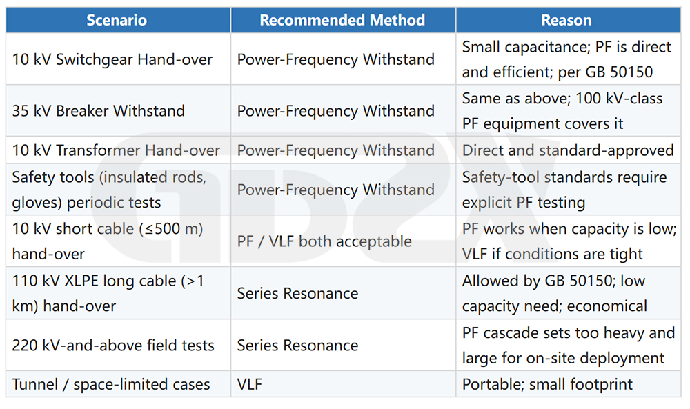
Core logic of selection:
Small test-object capacitance → prefer power frequency; large capacitance (long cables) → prefer series resonance; extremely limited site space → VLF as the fallback. Each method has its own scope of recognition in the standards; there is no absolute conclusion as to “which is more advanced” — only the engineering judgment of “which suits the current scenario”.
Chapter 06
06 | In-Depth Comparison of the Three Types of Test Transformers: Oil-Immersed, Gas-Filled (SF₆), Dry-Type |
Test transformers are the core component of the power-frequency withstand test system. By insulation medium and construction, they fall into three major types: oil-immersed, gas-filled (SF₆), and dry-type. Each has its own applicable scenarios; selection requires comprehensive consideration of the test object, operating environment, maintenance conditions, and environmental requirements.
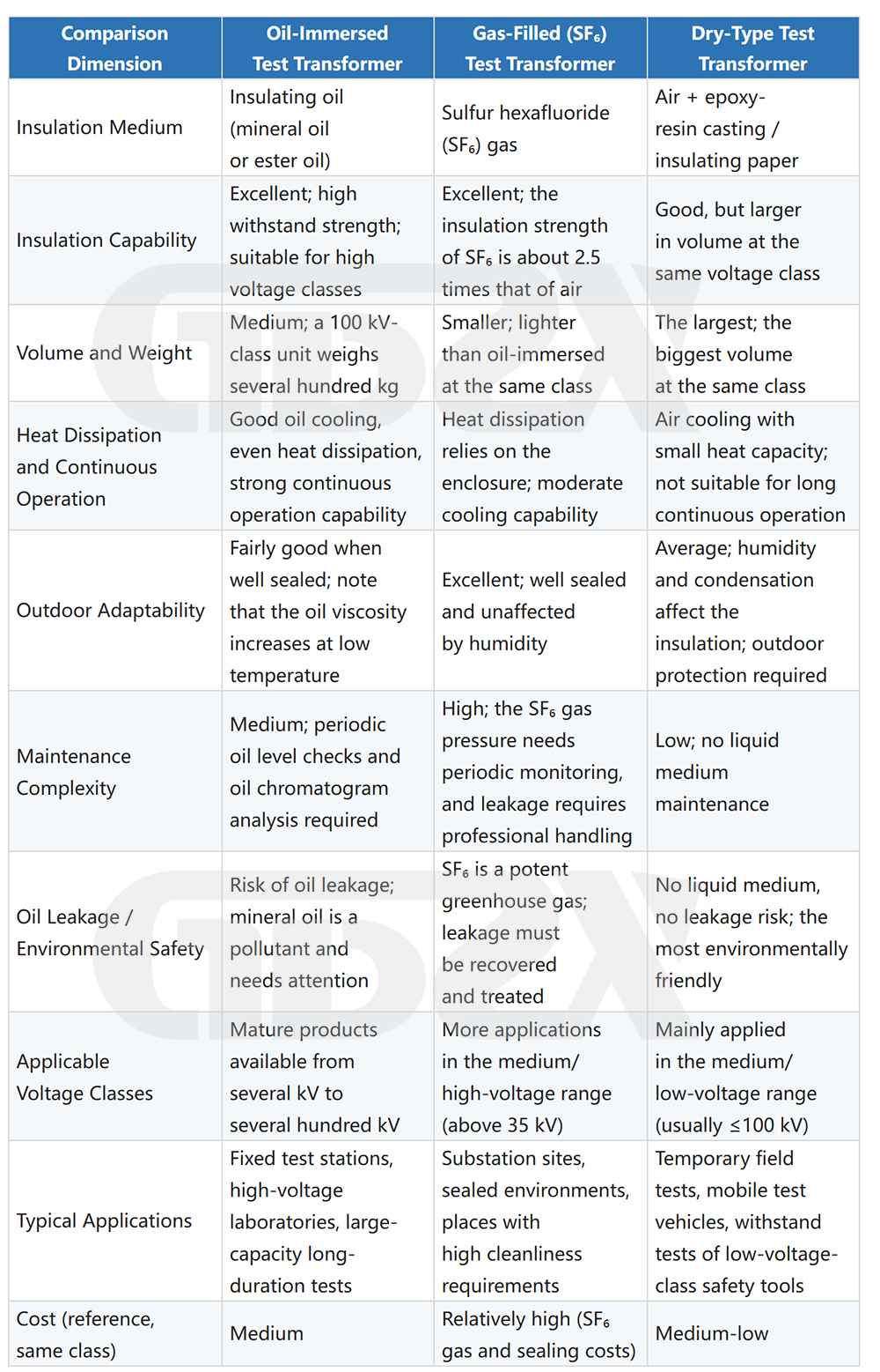
6.1 All-Dimension Comparison of the Three Transformer Types
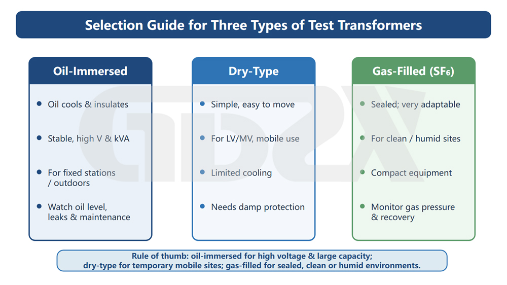
Figure 4 Selection diagram of the three types of test transformers
6.2 Field Selection Recommendations
Oil-Immersed — the First Choice for High Voltage and Large Capacity
The oil-immersed test transformer is the longest-established and most technically mature route among power-frequency withstand test equipment. Its core advantage is that the insulating oil serves both cooling and insulation functions: the oil has a large heat capacity and dissipates heat evenly, allowing the equipment to maintain stable continuous operation under high voltage (above 100 kV) and relatively large capacity — the rated continuous operating time is usually 30 min or more (subject to the product specification), more durable than dry-type units. The main equipment of fixed test stations and high-voltage laboratories is usually oil-immersed.
Applicable environment: ambient temperature -25℃ to +40℃, relative humidity ≤90% (non-condensing), altitude ≤1000 m (derating required at high altitude). The oil viscosity increases at low temperature; below -15℃, verify the low-temperature starting performance. Transport the unit upright or at the specified tilt angle to prevent oil leakage and winding displacement; perform a no-load operation check before the first use after installation.
Gas-Filled — Sealed Sites and Humid Environments
Gas-filled (SF₆) transformers have clear advantages at substation sites, GIS rooms and other places with high cleanliness requirements or high ambient humidity: the sealed enclosure completely isolates atmospheric humidity and is unaffected by relative humidity, so the unit can operate normally even where the relative humidity approaches 100% — something neither oil-immersed nor dry-type units can easily achieve. In addition, the insulation strength of SF₆ gas is about 2.5 times that of air at the same pressure (at a filling pressure of 0.3 MPa), effectively reducing the equipment volume.
Notes for use: the normal working gas filling pressure is generally 0.2–0.4 MPa (gauge pressure, subject to the product specification), which must be monitored regularly via the pressure gauge; operation below the lower pressure limit is not allowed. The global warming potential (GWP) of SF₆ is 23,500 times that of CO₂; leakage must be handled with dedicated recovery equipment, and direct release is strictly prohibited; decommissioned equipment must be entrusted to qualified organizations for gas recovery and disposal. As environmental regulations become stricter, some regions and projects have restricted the use of SF₆ equipment; confirm local policies before procurement.
Dry-Type — Mobile Sites and the Medium/Low-Voltage Range
With a simple structure and no liquid medium, dry-type test transformers are easy to transport and are a common configuration for mobile test vehicles and temporary field tests. Their main technical boundaries are as follows:
• Cooling limitation: air natural cooling with a small heat capacity; the rated continuous operating time is usually 5–15 min (subject to the product specification); beyond that, the unit must be stopped and cooled before continuing; not suitable for high-current, long-duration continuous testing;
• Humidity requirement: the recommended relative humidity for the operating environment is ≤80%; above 85%, the surface creepage risk of the insulation increases significantly; under condensation conditions (e.g., moving the unit from a low-temperature outdoor environment into a warm indoor one), wait until the equipment temperature is uniform before use;
• Applicable voltage: dry-type products are mainly rated ≤100 kV; at higher voltage classes they become too bulky and structurally complex, and are less economical than oil-immersed units.
|


