


NEWSnews
Power-Frequency Withstand Test: Control Setup, Test Procedure & Criteria
Chapter 07
07 | Control Box vs. Control Console: Key Differences Between the Two Control Units |
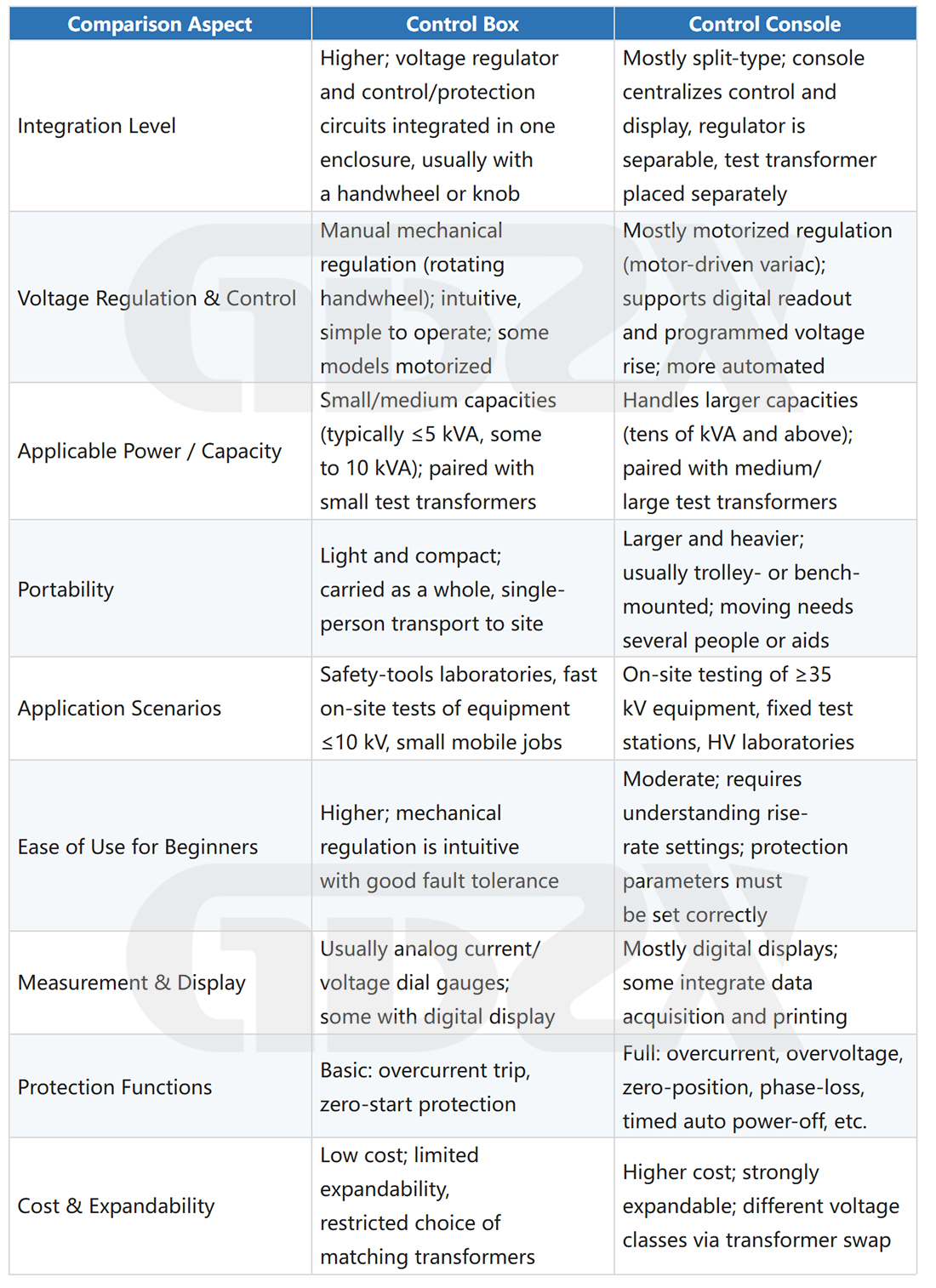
When purchasing power-frequency withstand test equipment, “control box” and “control console” are two easily confused concepts. Both provide control and protection functions for the test transformer, but they differ significantly in terms of integration, power capacity, and application scenarios.
7.1 Comprehensive Comparison
7.2 Selection Recommendations
withstand testing of equipment rated below 10 kV, a control box with a small test transformer is the most economical and practical solution, offering lower cost, portability, and easy operation.
If you need to cover equipment rated above 35 kV, higher-capacity test tasks, or fixed laboratory use, a control console with a dedicated test system is more suitable. Motorized voltage regulation can reduce manual operating errors, while the automatic timer and power-off function are particularly useful for withstand tests requiring a 1-minute duration.
How to Determine the Appropriate Overcurrent Protection Setting? The overcurrent protection setting on the control console/box should be determined based on the normal leakage current level of the test object. The general principles are as follows: ① First, determine the normal leakage current range of the type of test object at the test voltage, referring to historical data from similar tests or the manufacturer's technical documentation. ② The setting value should be above the normal leakage current with an appropriate margin to avoid false trips caused by fluctuations in normal charging current, while remaining below the current level that may occur during breakdown. The specific multiplier depends on factors such as the capacitance of the test object, equipment type, test method, and the manufacturer's protection logic. There is no fixed formula; the setting should be determined based on engineering experience and the manufacturer's recommendations. ③ For a new test object, the initial setting can be slightly conservative (set relatively low) and adjusted after its normal characteristics are established. ④ The setting should not simply be set to the maximum value—that would effectively eliminate the protection function. Refer to the applicable standards and equipment operating manual for the specific setting. The permissible leakage current varies among different types of test objects. |
Chapter 08
08 | Typical Power-Frequency Withstand Test Operating Procedure |
The following examples illustrate the complete operating procedures for a 35 kV circuit breaker power-frequency withstand test (on-site commissioning test) and a 10 kV insulating rod power-frequency withstand test. The prerequisites are that the test plan has been approved, safety measures have been implemented, and all personnel are properly qualified.
8.1 Pre-Test Preparation
1. Verify Standards and Test Voltage: Confirm the type and rated voltage of the test object, refer to the applicable sections of GB 50150 or DL/T 596, and determine the specified test voltage and duration for the test. Requirements vary by equipment type and must not be applied generically.
2. Check Environmental Conditions: Record the temperature and humidity during the test. Relative humidity should preferably be ≤80%. Excessive humidity may cause surface flashover or leakage along the test object's surface, affecting the results. Testing should be suspended during extremely humid conditions or appropriate drying measures should be taken.
3. Preliminary Insulation Resistance Measurement: Use a megohmmeter to measure the insulation resistance. If the measured value is abnormal, identify and resolve the issue before applying the test voltage.
4. Check Equipment Connections: Ensure that the test transformer's core and enclosure are reliably grounded with independent grounding, without mixing the grounding connection with the high-voltage measurement circuit. Check that the high-voltage output conductor is properly insulated and free of damage or exposed sections.
5. Return the Voltage Regulator to Zero: Confirm that the voltage regulator handle/knob is in the zero position to ensure that high voltage will not be output immediately after the power is switched on.
6. Set the Overcurrent Protection: Set the overcurrent protection value appropriately according to the type of test object (see Chapter 7).
7. Set Up Safety Barriers and Warning Signs: Install safety barriers and display “HIGH VOLTAGE—DANGER” warning signs. Keep unauthorized personnel outside the designated safe distance.
8.2 Voltage-Rising and Timing Stage
1. Switch On the Power: After confirming safety through verbal call-and-response, switch on the power supply of the control box/console.
2. Slowly Increase the Voltage: Starting from zero, turn the voltage regulator handle at a steady rate (or use motorized voltage regulation) to increase the voltage smoothly. The test standard requires the voltage rise rate to be no more than 3% of the full-scale value per second. For example, reaching 42 kV should take approximately 20–30 seconds. Avoid sudden voltage application.
3. Monitor the Instruments: Closely monitor the ammeter during voltage rise. The current should increase steadily. If a sudden fluctuation or sharp increase occurs, immediately reduce the voltage and investigate the cause.
4. Reach the Test Voltage and Start Timing: Once the high-voltage meter reaches the specified value, maintain the voltage within the required stability range (within ±3%) and start the timer simultaneously. The duration is typically 60 s (1 min). Some standards or safety tools may specify different durations; the applicable requirements shall prevail.
5. Monitor Throughout the Test: Monitor the ammeter and high-voltage meter throughout the timing period and record the test data. If discharge sounds are heard, the current increases sharply, or the protection device trips, immediately reduce the voltage and record the observed phenomenon.
8.3 Voltage Reduction, Discharge, and Test Completion
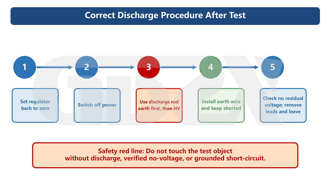
Figure 5. Correct Discharge Procedure After the Test
1. Reduce the Voltage Gradually After Timing Is Complete: Do not switch off the power abruptly. Slowly return the voltage regulator to the zero position before switching off the power supply. Sudden power interruption may cause switching overvoltage, potentially subjecting the test object to additional electrical stress.
2. Discharge: After the power supply is switched off, residual charge may remain at the high-voltage terminal, especially when testing capacitive test objects. The high-voltage terminal must be fully discharged to ground using a discharge rod or discharge resistor. Personnel must not touch the test object before discharge is completed.
3. Special Precautions for PTs (Potential Transformers): Inductive equipment such as PTs may generate relatively high induced voltages during discharge. The discharge rate must not be too fast. Use a dedicated discharge resistor or follow the discharge procedure specified in the equipment manual.
4. Remove Connections and Restore Safety: Only after discharge is complete and safety has been confirmed may the high-voltage leads be removed and the safety barriers taken down.
5. Record and Issue the Test Report: Record the test time, environmental conditions, test voltage, withstand duration, leakage current, and whether any discharge occurred, and then issue the test report.
8.4 Sectional Withstand Testing—Using Insulating Rods Rated Above 220 kV as an Example
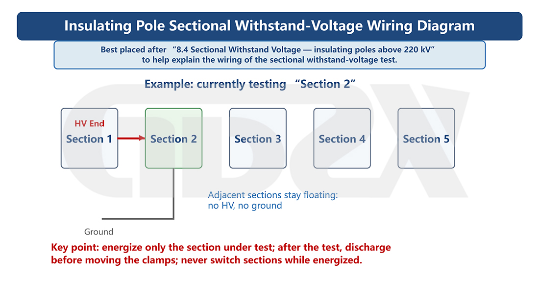
Figure 6. Wiring Diagram for Sectional Withstand Testing of Insulating Rods
Long insulating rods, such as 220 kV operating rods, can reach a total length of 3–5 m. Full-length withstand testing requires higher equipment capacity and more demanding test conditions, so sectional withstand testing is commonly used on site.
Key Points for Sectional Withstand Test Connections: ① Divide the insulating rod into sections of the specified length, and apply the test voltage to each section separately, in accordance with the applicable standard or test procedure. ② During the test of each section, connect the two ends of the test section to the high-voltage and ground terminals, respectively. Adjacent sections should remain suspended without connection to ground or high voltage to prevent parallel paths from affecting the test. ③ The test voltage and withstand duration for each section shall comply with the applicable standard for the insulating rod, such as GB 13398. ④ During connection, ensure that the high-voltage lead does not accidentally contact sections that have already passed the test or any operating personnel. ⑤ After each sectional test is completed, fully discharge the test section before moving the clamps. Moving clamps while the equipment is energized is strictly prohibited. Note: The specific sectional arrangement and test voltage must be determined according to the applicable current testing standard for the insulating rod under test. Requirements vary depending on the voltage rating and type of insulating rod. |
8.5 Safety Distance Requirements
The safety distance between personnel and energized parts during a power-frequency withstand test involves two aspects:
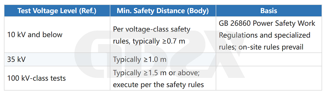
Important: The above information is for illustrative purposes only. The actual safety distance at the test site must be determined in accordance with the currently applicable local electrical safety work regulations, such as GB 26860 or the corresponding regulations of State Grid or China Southern Power Grid, based on the requirements for the applicable voltage level. The high-voltage output of the test transformer determines the applicable safety distance level. The safety distance is based on the test voltage, not the rated voltage of the power system. |
Chapter 09
09 | Test Criteria, Data Interpretation & Common Misconceptions |
9.1 Acceptance Criteria for Power-Frequency Withstand Tests
The common principle across standards for determining pass/fail in power-frequency withstand tests is:
Core Criterion: The test object passes the withstand test if, at the specified test voltage and for the specified duration, no breakdown occurs, no sustained partial discharge is observed, and no abnormal sudden change in leakage current occurs. |
1. Breakdown: The most obvious failure—protective devices trip, or a clear discharge sound accompanied by arcing is heard, indicating insulation failure and test failure.
2.Abnormally Increased Leakage Current: If the ammeter reading continues to rise or changes abruptly during voltage application or the withstand period, this may indicate thermal defects or progressive insulation breakdown.
3.Stable but High Current: Pass/fail determination depends on whether the current exceeds the limit specified in the applicable standard; requirements vary by equipment type.
4.No Abnormalities: The test is considered passed if there is no breakdown or sustained discharge during the test, the current remains stable, and the specified test duration is met.
9.2 Interpreting Ammeter Readings
This is one of the most common questions encountered on site: Does the ammeter read amperes (A) or milliamperes (mA)? Most power-frequency withstand test equipment uses milliampere (mA) ranges, while safety equipment tests may sometimes use **microampere (μA) ranges. Always check the unit marking on the meter scale rather than estimating based on the reading. In general, for equipment such as switchgear and transformers, leakage current below several milliamperes is typically considered normal; for insulating gloves and similar safety equipment, readings are generally in the microampere to sub-milliampere range. However, the specific pass/fail limit **must be determined according to the applicable standard; there is no single value that applies to all equipment. |
9.3 Impact of Ambient Humidity on Test Results
Testing withstand voltage in humid environments is a common challenge on site. The effects of humidity mainly include:
1. Surface Creepage on the Test Object: At high humidity, a water film may form on the surfaces of insulators, bushings, and other components, reducing the inception voltage of surface discharge and potentially making the test results less reliable.
2. Reduced Air-Gap Breakdown Voltage: The dielectric strength of humid air is lower than that of dry air, reducing the safety margin of air gaps around the test equipment and connections.
3. Reduced Insulation of Instruments and Connections: Moisture on the surfaces of high-voltage leads and voltage dividers can increase stray current and affect measurement accuracy.
GB/T 16927.1 specifies the requirements for test environmental conditions. When conditions fall outside the specified range, they should be recorded in the test report, and the results should be corrected or the test repeated as required. Relative humidity is generally required to be ≤80%; specific requirements shall be based on the applicable standard provisions.
9.4 Common Misconceptions Corrected
Q: Misconception: There is no need to discharge the test object after a power-frequency withstand test; it is safe to touch it once the power is switched off.
A: Incorrect. For test objects with capacitive characteristics, such as cables and capacitors, as well as large switchgear, residual charge may remain on the high-voltage terminal after the power is switched off. Inductive test objects, such as transformers and PTs, may also have induced voltages. The test object must be adequately discharged to ground using a discharge rod, and it must be confirmed that no residual voltage remains before it is touched.
Q: Misconception: The lower the leakage current, the better; high-quality insulation should have leakage current close to zero.
A: Not necessarily. Insulating materials inherently have a certain dielectric loss, so leakage current cannot be expected to be zero. The key factors are that the leakage current remains within the specified limit and stable during the withstand period, rather than simply being as low as possible. An abnormally low reading may sometimes indicate a poor connection in the voltage divider or measurement circuit.
Q: Misconception: A power-frequency withstand test is simply a high-voltage test using a DC high-voltage generator.
A: Completely different. A power-frequency withstand test applies 50 Hz sinusoidal AC high voltage, whereas a DC high-voltage generator outputs DC high voltage. Their operating principles, applicable test objects, and acceptance criteria are different, and they cannot be used interchangeably except where explicitly permitted by the applicable standard.
Q: Misconception: The overall withstand voltage and open-gap withstand voltage of a 35 kV circuit breaker are the same.
A: They are different. The insulation requirement across the open gap between the contacts in the open position is higher than the insulation requirement to ground. The withstand voltage across the open gap is therefore typically higher than the overall withstand voltage. Specific values shall be checked separately against the applicable provisions of Chapter 10 of GB 50150 and the corresponding provisions of DL/T 596; they must not be used interchangeably.
Q: Misconception: The test voltage for commissioning (handover) tests and preventive tests is the same.
A: They are generally different. Commissioning tests are performed for acceptance of new equipment and normally use higher test voltages, while preventive tests are conducted periodically on equipment in service. To reduce cumulative stress on insulation, preventive test voltages are generally lower than commissioning values. DL/T 596 specifies preventive test voltages for different types of equipment; specific requirements shall be checked against the applicable provisions.


