


NEWSnews
Power-Frequency Withstand Test: Faults, FAQs & Standards
10 | Common Fault Symptoms and Troubleshooting Approach |
The following fault symptoms are based on real-world field scenarios. Each item provides an initial troubleshooting approach, but the final diagnosis should be based on the specific circumstances.
10.1 Abnormal Ammeter Reading During Voltage Rise
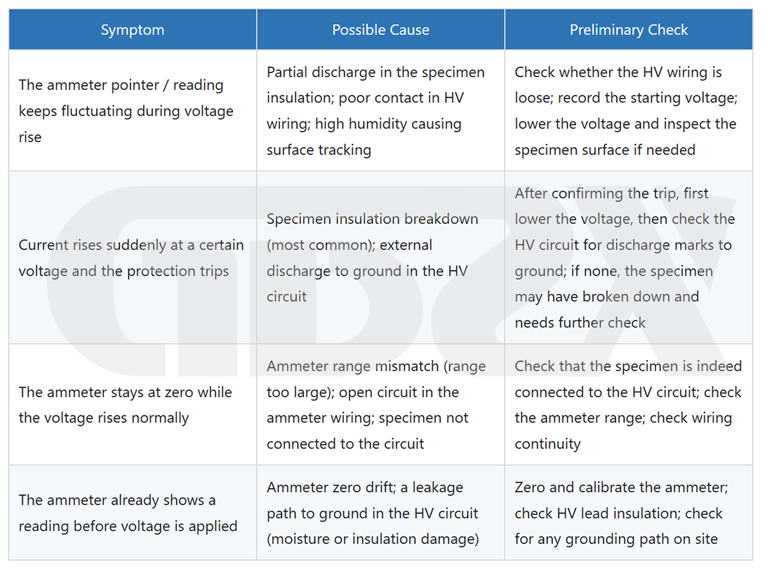
10.2 Abnormal High-Voltage Meter Reading
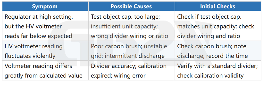
10.3 Protection Malfunction (Frequent Tripping Without Test Breakdown)
1.The overcurrent protection setting is too low, and the normal leakage current of the test object exceeds the set value → Increase the setting appropriately (but do not raise it blindly);
2.The voltage rise rate is too fast, causing surge current that triggers the protection → Reduce the voltage rise rate;
3.There are floating conductors or poor grounding in the high-voltage circuit, causing parasitic discharge → Check for and eliminate floating conductors, and ensure reliable grounding;
4.The protection circuit of the control box/console itself is faulty → Replace or send it for repair.
10.4 Test Transformer Overheating
When operated continuously for too long or when the capacity is seriously insufficient, the transformer may overheat. This is particularly noticeable with dry-type transformers. Recommended actions:
1.Check whether the rated continuous operating time has been exceeded, and allow adequate cooling intervals according to the equipment manual;
2.Confirm whether the capacity required by the test object significantly exceeds the rated capacity of the equipment. If so, use a higher-capacity unit;
3.If an oil-immersed transformer overheats, check the oil level and oil condition. If necessary, shut down the equipment for inspection.
11 | In-Depth Answers to Frequently Asked Questions |
The following questions are based on engineering practice and inquiries raised by customers during equipment use. They are organized by topic, with only technically valuable content retained.
【Standards-Related Questions】
Q: What is the withstand test voltage for a 10 kV transformer? Is there a formula?
A: The power-frequency withstand test voltage for a 10 kV power transformer should be determined by referring to the applicable clauses for the corresponding rated voltage level in Chapter 6 of GB 50150 (handover tests) or Chapter 6 of DL/T 596 (preventive tests), and verified against the factory test report. The test voltage depends on the transformer’s rated voltage, insulation level (Um), and whether the test is a factory, handover, or preventive test.
As for whether there is a formula: the test voltage values corresponding to different voltage levels and insulation levels are specified in standard tables rather than calculated using a single universal formula. A general principle is that the factory test value is multiplied by a coefficient (approximately 100% for handover tests and 75%–80% for preventive tests). However, the specific requirements of the applicable standard take precedence, and these coefficients must not be used to derive unsupported values.
Q: What is the handover test voltage for a 35 kV circuit breaker? Why is the voltage across the open contacts sometimes specified as 48 kV, while the overall voltage is 42 kV?
A: These two values represent different insulation requirements for the open contacts and the overall insulation to ground; they are not contradictory. When the circuit breaker is open, the insulation between the moving and stationary contacts must withstand the potential difference that may occur across the two sides. Therefore, the insulation requirement across the open contacts is generally higher than the overall insulation to ground. The specific values should be determined according to the currently effective version of Chapter 10 of GB 50150. Specific values are not listed here because they may change with revisions to the standard; the original standard should be consulted.
Q: How long should the withstand test on a switchgear be performed?
A: The duration of a power-frequency withstand test for most equipment is 1 min (60 s) for both handover and preventive tests, as specified in most equipment-related clauses of GB 50150 and DL/T 596. For safety tools and equipment, the specified duration may sometimes be 1 min or 3 min, depending on the applicable standard. The test is judged based on whether the specified voltage is maintained for the specified duration without breakdown or abnormality, rather than by arbitrarily extending the test duration.
Principle-Related Questions
Q: Where does the voltage for a power-frequency withstand test come from?
A: Starting from the utility power supply (220 V/380 V), a variable autotransformer, which can be adjusted from zero, supplies the low-voltage winding of the test transformer. The test transformer then steps the voltage up to the required high voltage, ranging from several kV to several hundred kV. In essence, the voltage comes from the power grid, with the variable transformer controlling the output magnitude and the test transformer performing the voltage step-up.
Q: How long or how large a cable can a power-frequency withstand test system test?
A: The maximum cable length depends on two matching parameters: the rated voltage of the equipment (which must be ≥ the test voltage) and its rated capacity (which must be ≥ the reactive power consumed by the test cable at the test voltage). The longer the cable, the greater its capacitance and the higher the required capacity. In general, for 10 kV XLPE cables, a power-frequency test system in the hundreds-of-kVA range can typically cover several hundred meters. Beyond this range, the required capacity increases rapidly, making a series resonance system a more practical choice.
The specific calculation formula is provided in Chapter 2 of this article. The basic principle is to calculate the required capacity first and then select a matching test system, rather than simply using an existing system to “see whether it works.”
Q: Why can't long cables be tested directly with power frequency and instead require series resonance?
A: It is not that power frequency cannot be used; rather, it is economically impractical. Testing capacitive test objects at power frequency requires a large amount of reactive power. As cable length and capacitance increase, the required test transformer capacity also increases, potentially reaching thousands of kVA or more, making the equipment costly and impractical to transport and operate on site. Series resonance uses resonance between the inductor and the capacitance of the test object, so the power supply mainly needs to provide the losses (active power). The required capacity can therefore be reduced to approximately 1/Q of that required by power-frequency testing (where Q is the quality factor, typically 20–50). Consequently, series resonance is more efficient and cost-effective for large-capacitance test objects.
Operation-Related Questions
Q: Is discharge required after the test? How should a PT be discharged?
A: Yes. After the test voltage is reduced and the power is switched off, residual charge may remain on the test object, particularly for capacitive test objects. Direct contact may result in electric shock. Discharge should be performed using a discharge rod, with the grounding end connected to ground and the discharge end contacting the high-voltage conductor.
A PT (potential transformer) is an inductive device. If discharged too quickly, the release of magnetic energy may generate a relatively high induced voltage. A PT should therefore be discharged through a dedicated discharge resistor, with an appropriate resistance connected in series before grounding, allowing the energy to be released gradually and avoiding dangerous overvoltage. The high-voltage terminal must not be directly short-circuited to ground with a wire.
Q: What personal safety precautions should be taken during operation?
A: High-voltage testing requires a systematic safety control approach. Key measures include barriers and warning signs to prevent unauthorized personnel from entering the test area, interlocking devices to prevent high-voltage application when a door is open, remote operation and supervision, and discharge confirmation to ensure that the test object has been fully discharged before personnel approach it. For personal protection, operators should stand on an insulating mat, wear insulating footwear, and, where appropriate, wear insulating gloves. Note that standing on an insulating mat is only one protective measure and cannot replace systematic safety measures such as barriers and interlocks. Specific site safety requirements should comply with GB 26860, Safety Regulations for Electric Power Industry, and applicable specialized safety procedures.
Q: Is this an AC or DC test? What is the difference between it and a DC high-voltage generator?
A: A power-frequency withstand test is an AC high-voltage test that applies a 50 Hz sinusoidal AC voltage. A DC high-voltage generator outputs DC high voltage. The two differ in their test objects, evaluation criteria, and applicable standards. The key value of power-frequency withstand testing is that the test frequency corresponds to the operating frequency, while DC high-voltage generators are commonly used for DC withstand or leakage current tests on cables. Unless explicitly permitted by the applicable standard, DC test results cannot be used to replace the conclusion of a power-frequency AC handover test.
Safety-Related Questions
Q: Is power-frequency withstand testing dangerous? What qualifications are required?
A: Yes. Power-frequency withstand testing involves significant hazards. The test voltage is far higher than the human body safety voltage (36 V or below). Contact with energized components can immediately result in severe electric shock or even death. Therefore, all operations must strictly comply with applicable safety regulations.
Regarding qualifications, in China, personnel performing high-voltage testing generally need to hold a High-Voltage Electrical Work Special Operation Certificate issued by the relevant emergency management authority. Some organizations and projects may also require an electrical testing qualification for entry into the power industry. Specific qualification requirements should be verified according to local regulatory requirements and the rules of the employing organization. The high-voltage electrician certificate is a basic requirement, while additional qualifications depend on the specific type of work and organizational requirements.
Q: Will humid conditions affect a 95 kV test or other high-voltage tests?
A: Yes, and the impact can be significant. Under high-humidity conditions: ① the creepage path along the surface of the test object may become more susceptible to surface discharge, potentially causing flashover before the specified test voltage is reached and resulting in an incorrect failure judgment; ② the insulation performance of the test equipment itself, such as high-voltage leads and voltage dividers, may also deteriorate; and ③ measurement accuracy may be affected. GB/T 16927.1 specifies test environmental conditions, including temperature and humidity. If these conditions are exceeded, the test results should be documented in the report, and retesting should be considered. In practice, high-voltage tests should be postponed during rain, heavy fog, or other high-humidity conditions, or measures such as drying the test object and installing a moisture-proof shelter should be taken.
Selection-Related Questions
Q: How should I choose between a power-frequency withstand test system and a very-low-frequency (VLF) test system? Can VLF replace power frequency for handover tests?
A: It cannot be replaced arbitrarily. Very-low-frequency (VLF, 0.1 Hz) withstand testing is permitted by certain standards for specific test objects, such as cables, in preventive tests or certain handover test scenarios. However, its applicable scope and acceptance conditions are subject to specific requirements. It is not simply a matter of using the same function at a different frequency. VLF and power-frequency testing involve different stress mechanisms, and the comparability of their test results is limited.
The general principles are: ① VLF may replace power frequency only where the applicable standard explicitly permits it; ② if the standard does not provide for such substitution, power frequency should be used as the basis for handover testing; and ③ for cable handover tests and large-capacitance equipment, the applicable standard and its provisions on alternative test methods should be consulted.
12 | Article Self-Review and Error Correction Statement |
During the preparation of this article, every effort was made to follow the principles below. However, readers should still exercise independent judgment when applying the information in actual practice.
12.1 Principles for Citing Standards
1.All standards cited in this article are based on the versions that were currently effective at the time of writing. Standards are subject to periodic updates and revisions. Readers must verify the current effective version of each cited standard before conducting actual tests, and the latest officially issued version shall prevail;
2.This article deliberately does not list specific test voltage values (except for example calculations provided for explanatory purposes), because the applicable voltage values vary depending on the equipment, voltage level, and type of test. Providing a “unified value” could mislead readers into applying it indiscriminately;
3.References to standards in this article indicate the applicable clause ranges. Readers should consult the original standard clauses directly rather than treating the generalized descriptions in this article as a substitute for the original standards.
12.2 Potential Limitations of This Article
1.The power industry standards system is complex. Different power grid companies and provincial-level organizations may have supplementary regulations in addition to national standards. This article cannot cover all local requirements;
2.Tests involving safety tools and equipment are subject to standards such as the GB 13398 series and various provincial safety regulations. This article provides guidance only at a general level;
3.Descriptions of equipment parameters in this article are for general reference. Specific product parameters shall be based on the manufacturer’s technical documentation;
4.The operating procedures described in this article are provided for general reference. Actual on-site operations shall comply with applicable site safety regulations and approved test plans.
12.3 If Readers Identify Errors
If you identify any errors in standard references, inaccurate data, or inappropriate wording in this article, feedback is welcome. The power testing standards system is highly specialized, and any technical article may contain deviations resulting from simplified explanations. For actual engineering decisions, the original provisions of the applicable standards shall always be the final basis.
Disclaimer: This article is provided for educational and reference purposes only and does not constitute an operational guide for testing. All high-voltage tests must be performed by qualified professionals in accordance with currently effective standards and approved test plans, with comprehensive safety measures in place. The author assumes no responsibility for any consequences arising from conducting high-voltage testing based directly on the content of this article. |
13 | Referenced Standards and Applicability Boundaries |
13.1 List of Main Standards Referenced in This Article
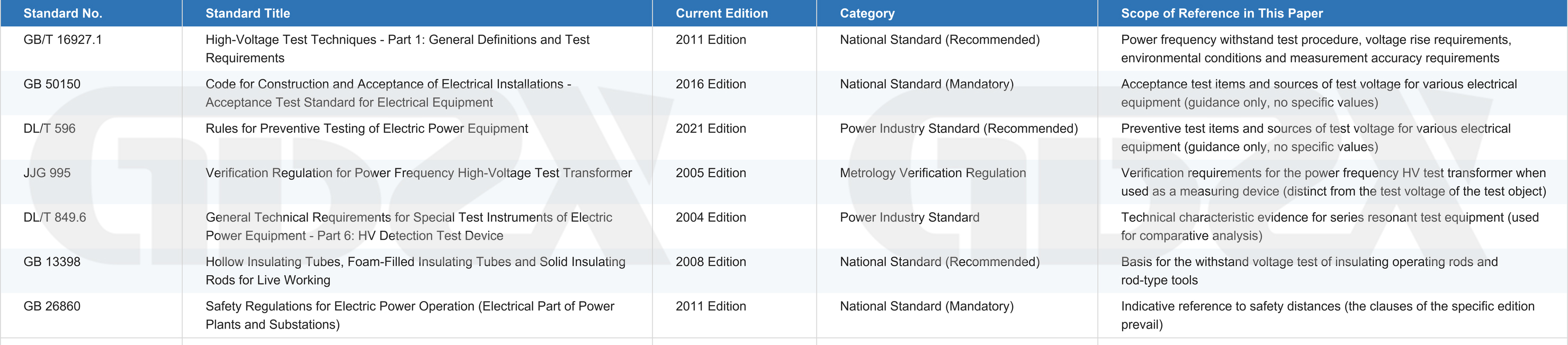
13.2 Applicability Boundaries for Using This Article
The following scenarios are beyond the scope of this article for direct operational guidance. The original applicable standards must be consulted: 1. Confirmation of test voltage values for any specific equipment; 2. Special requirements for test voltage duration, including cases other than the default 1 min; 3. Determination of the disposition and follow-up actions after a test object fails; 4. Specific conditions under which very-low-frequency (VLF) or series resonance testing may replace power-frequency testing; 5. Correction methods for special environmental conditions, such as high altitude, extremely low temperatures, or unusual climatic conditions; 6. Requirements specified in supplementary regulations issued by individual provinces, regions, or organizations. |
13.3 Standards Validity Notice
Power industry standards are subject to frequent revisions. Readers should verify the current effective version of the standards cited in this article before use. It is recommended to confirm their validity through the technical standards department of the relevant power grid company or the official channels of the standards-issuing organizations.
Article writing date: 2026 | Scope: China Mainland power industry | Main standards referenced: GB/T 16927.1—2011, GB 50150—2016, DL/T 596—2021
If any of the above standards have been revised or updated, the latest effective version shall prevail. Before use, please verify their validity through the National Public Service Platform for Standards Information.


