


NEWSnews
Simulated Circuit Breaker: Selection & Protection Testing
一、Before Purchasing: Switching Contacts Does Not Mean Supporting Full-Group Testing
Many procurement requests specify “purchase one circuit breaker simulator,” with the justification that it is “required for complete protection system testing.” When asked what the equipment is used for, the procurement manager answers, “To switch circuit breaker contacts.” This understanding is not wrong, but it captures only 10% of the actual requirements.
What Must a Circuit Breaker Do During a Complete Protection System Test?
In accordance with applicable inspection procedures, such as DL/T 995, a complete relay protection system test verifies the entire closed-loop process, from the protection device detecting fault quantities to completing the full operating logic. This closed loop requires the following:
1.After the protection device issues a trip command, the circuit breaker must respond within a specified time window—not at an arbitrary time.
2.After the circuit breaker responds, the TWJ (trip-position contact) and HWJ (close-position contact) must switch mutually exclusively, without entering a state in which both are zero or both are one.
3.Auxiliary contacts must switch synchronously with the breaker’s open/closed position, ensuring that the protection device receives the correct position feedback.
4.During a breaker failure protection test, the circuit breaker must be able to receive a trip command without operating (failure-to-trip mode).
5.During a busbar differential protection or automatic bus transfer test, multiple circuit breakers must operate in coordination according to the designed timing sequence, rather than operating independently at arbitrary times.
Which of these five requirements can manual jumper wires or a simple contact conversion board actually meet?
Requirement 1: No. Manual switching introduces errors of hundreds of milliseconds, making the timing sequence invalid.
Requirement 2: No. Manual switching inevitably passes through a state in which both contacts are zero, with an unpredictable duration.
Requirement 3: No. Manual switching cannot ensure that auxiliary contacts change synchronously with the breaker’s open/closed position.
Requirement 4: No. It cannot reliably reproduce the condition in which a trip command is received but the circuit breaker does not operate.
Requirement 5: Absolutely not. Timing errors resulting from coordination among multiple operators cannot meet the requirements of the applicable procedures.
Conclusion: Manual jumper wires and contact conversion boards address the question of “whether a signal is present.” A circuit breaker simulator addresses the question of “whether signals switch according to the correct logic at the correct time.” The former is suitable for preliminary wiring checks, while the latter enables valid complete protection system testing.
This is why “being able to switch contacts does not mean being capable of complete protection system testing.” The core requirements of a complete system test are timing accuracy, logical integrity, and repeatability—not merely whether contacts are available.
二、What Problem Does It Solve in the Procurement Process
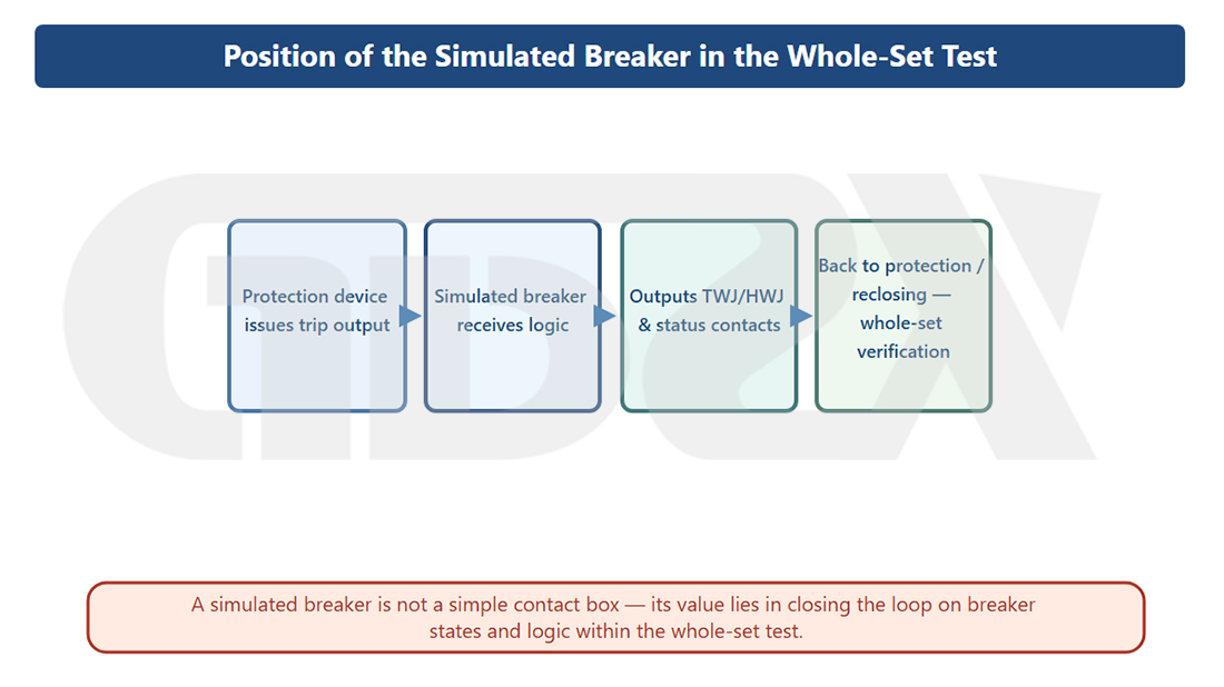
Illustration: The Role of a Circuit Breaker Simulator in Complete Protection System Testing
2.1 Position in the Complete Protection System Test Circuit
Signal Flow in a Standard Relay Protection System Test Circuit:
Relay Test Set Outputs Simulated Fault Quantities
↓
Protection Relay Detects Fault Quantities and Makes a Decision
↓
Protection Relay Issues a Trip/Close Command
↓
【Circuit Breaker Simulator】 Receives Command
↓
Switches Open/Closed Position Contacts and Outputs Auxiliary Contact Signals
↓
Protection Relay Reads Back Position Feedback Signals, Completing the Protection Logic Loop
↓
Relay Test Set Records Operating Times and Waveforms
The circuit breaker simulator acts as a “controlled-device surrogate” in this circuit. It replaces the actual circuit breaker, allowing the protection relay to recognize that “the field circuit breaker has operated,” thereby completing the full protection logic sequence.
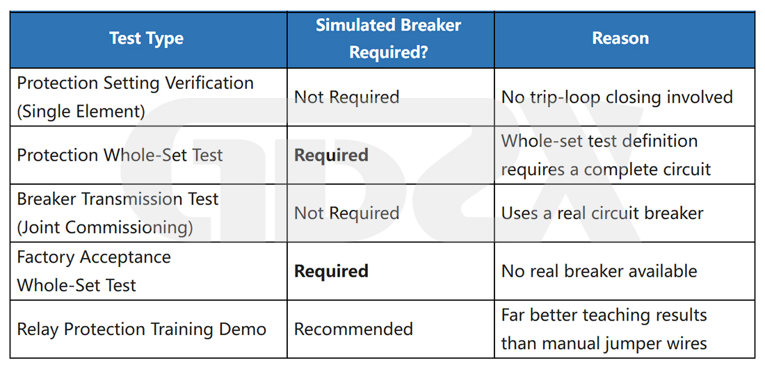
Without it, the complete protection test circuit remains incomplete. The protection relay can only perform individual protection element setting checks and cannot verify the end-to-end behavior of the entire protection scheme, from fault detection to circuit breaker operation feedback.
2.2 Its Role in the Procurement Process
A circuit breaker simulator is typically procured alongside the following equipment to form a complete relay protection system testing setup:
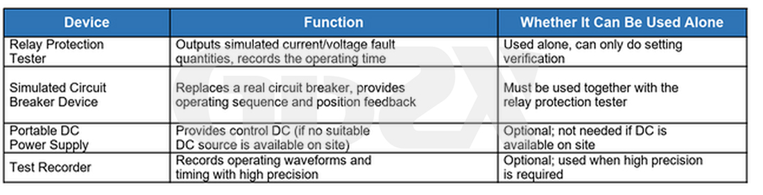
The key procurement principle: The relay test set determines what faults you can inject, while the circuit breaker simulator determines what logic you can verify. Even a high-quality relay test set cannot produce valid complete protection system test results when paired with a circuit breaker simulator that fails to meet the required specifications.
2.3 When a Circuit Breaker Simulator Is Required—and When It Isn’t
三、Procurement Differences Among Five Types of Complete Protection System Tests
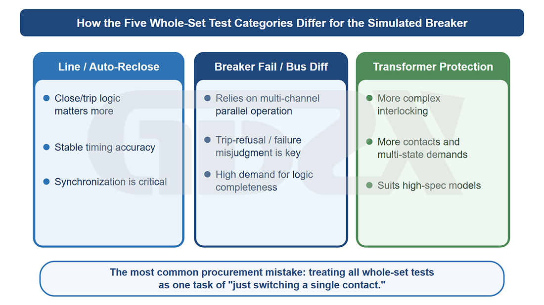
Illustration: Circuit Breaker Simulator Requirements for Five Types of Complete Protection System Tests
Requirements for circuit breaker simulators vary significantly across protection types. These differences are a key factor in determining the number of channels and functional configuration required for procurement.
3.1 Line Protection System Testing
Key Procurement Considerations: The fewest channels are required, but timing accuracy and the integrity of the autoreclosing sequence are critical.
Line protection system testing typically involves one circuit breaker, with either three-phase simultaneous operation or independent single-phase tripping. For three-phase autoreclosing, one channel is sufficient. For single-phase autoreclosing, three independent channels for phases A, B, and C are required to execute the complete sequence: “Phase A fault → Phase A trips → Phase A recloses → Phase A trips again,” while phases B and C remain independently controlled in the closed position throughout the process.
Verifying the autoreclosing sequence is a common requirement in line protection system testing. The simulator must reliably execute the complete sequence of “trip → maintain open position → receive close command → switch to closed position → trip again,” without missing commands or contact chattering during the process.
Minimum Configuration: Three independently controlled channels for single-phase operation (or one channel for three-phase simultaneous operation, depending on the protection configuration); continuously adjustable timing; timing accuracy within ±5 ms; and a wide-range DC power input.
3.2 Complete Busbar Differential Protection System Testing
Key Procurement Considerations: The largest number of channels is required, and multi-channel synchronization accuracy is critical. Multiple single-channel units should not be combined as a substitute for a dedicated multi-channel unit.
The core logic of busbar differential protection is to identify the faulted bay and trip all relevant circuit breakers. Complete system testing must simulate multiple circuit breakers across different bays simultaneously to verify that the busbar differential protection operates correctly (isolating the faulted bay) while avoiding maloperation (keeping healthy bays in the closed position).
A typical 220 kV busbar may have 6–8 bays, requiring 6–8 synchronized circuit breaker simulator channels. The biggest procurement pitfall is combining multiple single-channel units. The internal clocks of separate single-channel units are not synchronized, and timing differences can reach tens of milliseconds or more, potentially exceeding the synchronization tolerances required by applicable procedures for multi-breaker operation and invalidating the test results.
The core value of a dedicated multi-channel unit lies in its unified internal synchronization control. All channels share a common clock reference, allowing the synchronization deviation between channels to be controlled within 2 ms.
Minimum Configuration: A dedicated multi-channel unit (combining multiple single-channel units is not acceptable); number of channels ≥ number of bays; measured synchronization deviation between channels ≤ 2 ms; and independent opto-isolation for each channel.
3.3 Complete Automatic Bus Transfer System Testing
Key Procurement Considerations: Two independently controlled channels, precise timing coordination, and asynchronous operation capability.
Automatic bus transfer system testing verifies the complete logic sequence: “loss of the normal power supply → incoming circuit breaker trips → standby circuit breaker automatically closes.” The key requirement is precise coordination of the trip-before-close sequence: the standby circuit breaker can close only after the incoming circuit breaker’s opening has been confirmed, with strict timing requirements.
The two-channel device must support fully independent control of both channels (Channel A trips, Channel B closes, with the sequence and time interval independently adjustable), rather than simply triggering both channels simultaneously. If the purchased two-channel model supports only synchronized operation and cannot provide independent asynchronous control, it will also be unable to complete automatic bus transfer system testing.
Minimum Configuration: Two independently controlled channels supporting asynchronous operation (Channels A and B respond to their respective commands independently, without linked operation); continuously adjustable timing; and a wide-range DC power input.
3.4 Complete Circuit Breaker Failure Protection System Testing
Key Procurement Considerations: Failure-to-trip simulation is a mandatory requirement. Basic models do not provide this function, and it is non-negotiable.
The core purpose of complete circuit breaker failure protection system testing is to verify the following scenario: after the protection device issues a trip command, the circuit breaker fails to open within the specified time (failure-to-trip). Once the failure protection operating time has elapsed, the circuit breaker failure protection initiates a wider-area tripping sequence.
This test condition requires the circuit breaker simulator to receive a trip command without operating, maintaining the closed position. Ordinary simulators trip automatically upon receiving a command and therefore cannot reproduce the “command received, no operation” condition. Only devices supporting a “breaker failure/failure-to-trip mode” can perform this function. In this mode, even when a voltage pulse is applied to the trip input terminal, the internal relay does not respond, and the simulator maintains its existing position.
Minimum Configuration: Must support breaker failure/failure-to-trip simulation mode; maintain the current position unchanged while this mode is active; and reliably reset after failure-to-trip simulation ends. Basic models that do not meet these requirements should be excluded from consideration.
3.5 Complete Transformer Protection System Testing
Key Procurement Considerations: Select the number of channels according to the number of transformer sides, typically 2–3 channels, and ensure compatibility with non-electrical protection input signals.
Transformer differential protection requires simultaneous control of the circuit breakers on each transformer side (high-voltage, medium-voltage, and low-voltage sides). A two-winding transformer requires 2 channels, while a three-winding transformer requires 3 channels.
Non-electrical protection functions (such as main tank Buchholz protection, on-load tap changer Buchholz protection, and pressure relief protection) are typically simulated through independent dry-contact inputs. The device must provide sufficient compatible binary I/O channels rather than relying on the trip/close circuits for simulation. During procurement, confirm whether the device provides dedicated simulated contact outputs for non-electrical protection.
Minimum Configuration: Number of channels matched to the number of protected transformer sides (2 or 3 channels); independent control of each channel; and compatibility with non-electrical protection contact requirements.


