


NEWSnews
Simulated Circuit Breaker: Key Specs & Model Selection
四、6 Key Parameters to Check Before Purchasing
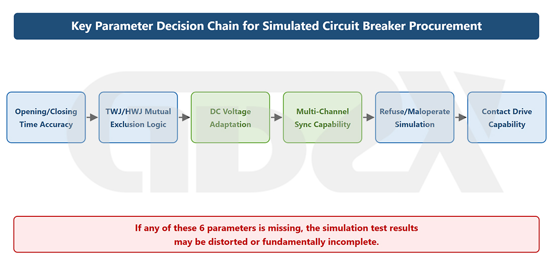
Illustration: Key Parameter Evaluation Workflow for Simulated Circuit Breaker Procurement
Parameter 1: Opening and Closing Time Accuracy (The Most Critical and Easily Misrepresented Parameter)
Why It Matters: The core data in a protection system-wide test is the protection operating time. The operating time is recorded by the relay protection tester, but the recorded value includes the operating delay of the simulated circuit breaker. This delay must be subtracted to obtain the actual operating time of the protection device:
t_{\text{protection}} = t_{\text{system-wide}} - t_{\text{SBU}}
where (t_{\text{SBU}}) is the measured and calibrated operating time of the simulated circuit breaker.
If the simulated circuit breaker has poor timing accuracy (with measured deviations of ±10 ms at the same setting across repeated operations), the uncertainty in the calculated protection operating time will be ±10 ms after the delay is subtracted. For protection functions with setting values of only 20–30 ms, this error is decisive and directly undermines the reliability of pass/fail judgments.
How to Identify Misleading Specifications: When a manufacturer claims an “accuracy of ±1 ms,” this can mean two different things:
1.“Setting accuracy ±1 ms”: The setting resolution is 1 ms, but the actual operating deviation may be much greater.
2.“Measured repeatability accuracy ±1 ms”: The deviation between actual measured results and the set value remains within ±1 ms. This is the genuinely meaningful accuracy specification.
How to Specify the Requirement in a Procurement Contract:
The measured repeatability error of the opening and closing operating times (defined as half the difference between the maximum and minimum values over 10 consecutive measurements at the same setting) shall not exceed ±X ms. The supplier shall provide an actual measurement and calibration report obtained using timing instruments with a resolution of 0.1 ms or better. The report shall include 10 measurements at each of at least five different time settings: 20 ms, 50 ms, 100 ms, 200 ms, and 500 ms. Manufacturer specifications stating only “setting accuracy” shall not be considered compliant with this requirement.
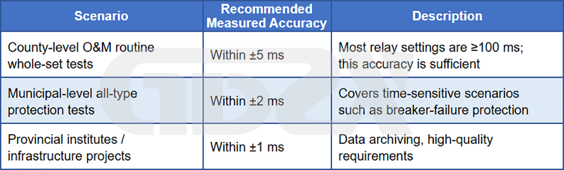
Recommended Accuracy for Different Applications:
Parameter 2: TWJ/HWJ Mutual Interlocking Logic (The Minimum Requirement for Logical Integrity)
Why It Matters: In a real circuit breaker, the TWJ (trip-position relay contact) and HWJ (close-position relay contact) follow a strict mutual interlocking logic:
1.Circuit breaker closed: HWJ = 1, TWJ = 0.
2.Circuit breaker open: TWJ = 1, HWJ = 0.
3.TWJ = 0 and HWJ = 0 are not permitted at any time (this triggers the “control circuit disconnection” alarm).
4.TWJ = 1 and HWJ = 1 are not permitted at any time (logical error).
Low-quality simulated circuit breakers may briefly enter a state in which both TWJ and HWJ are 0 during opening/closing transitions (a “dual-zero window”). This state can trigger a “control circuit disconnection” alarm in the protection device, causing false alarms and interfering with the evaluation of system-wide tests.
How to Verify: Require the manufacturer to provide TWJ/HWJ switching waveforms recorded using an oscilloscope or logic analyzer. Confirm that no dual-zero window occurs during switching, or that its duration is shorter than the protection device’s alarm detection time (typically, less than 5 ms is considered a safe range).
Parameter 3: DC Input Voltage Compatibility Range (Key to On-Site Compatibility)
Why It Matters: DC control voltages are not uniform across field installations. DC 110 V is the predominant control voltage in most substations in China. DC 220 V is used in some high-voltage substations (500 kV and above) and older 220 kV substations. DC 48 V is found in some communication power systems and substation retrofit projects.
A device designed for only one voltage (e.g., DC 110 V) cannot be used at a site requiring DC 220 V. Field teams have not infrequently had to suspend testing and procure power supply modules at short notice because of this incompatibility.
Procurement Recommendations:
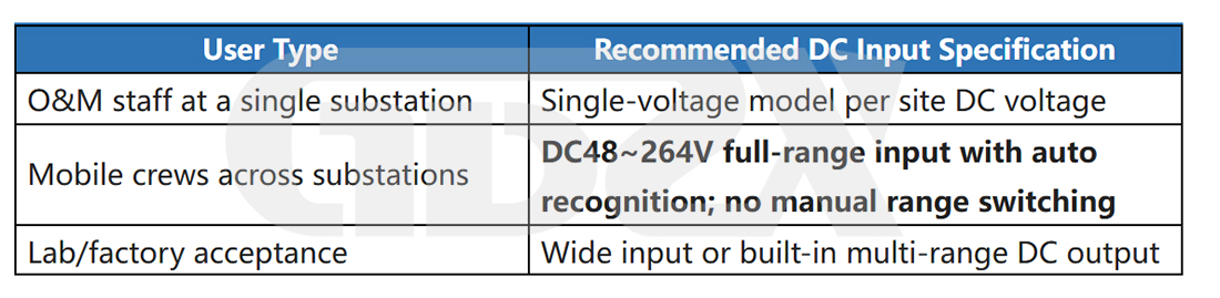
Note: Some manufacturers’ “wide-range input” designs actually rely on manually switching between voltage settings using DIP switches, rather than providing true automatic wide-range adaptation. The difference can significantly affect on-site usability. Procurement specifications should explicitly require “automatic voltage recognition with no manual switching required.”
Parameter 4: Number of Output Channels and Synchronization Accuracy (Critical for Multi-Circuit Breaker Testing)
Why It Matters: The number of channels determines which types of protection system-wide tests can be covered, while synchronization accuracy determines the validity of test results involving multiple channels.
Quick Reference for Channel Requirements:
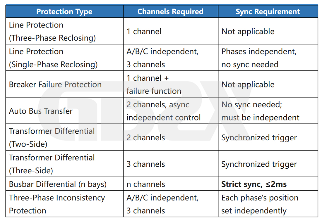
Core Principle of Multi-Channel Synchronization: For any application requiring multi-channel synchronization, a dedicated multi-channel model must be selected; combining multiple single-channel units is not acceptable. The timing differences between separately assembled units cannot be reliably controlled. In busbar differential protection system-wide tests, these deviations can directly distort differential calculations and invalidate the test results.
Parameter 5: Breaker Failure / Failure-to-Operate Simulation Capability (Essential for High-Value Applications)
Why It Matters: Breaker failure protection system-wide testing is one of the most difficult scenarios to reproduce during relay protection commissioning and one of the most effective ways to verify protection system integrity. Without a failure-to-operate simulation function, this test cannot be performed.
Key Functional Verification Points:
1.In failure-to-operate mode, when a normal voltage pulse is applied to the trip input, does the device genuinely remain inactive? Verify the contact status using a logic analyzer.
2.Can the failure-to-operate duration be configured? The breaker failure initiation time is typically 0.15–0.25 s, and the device must maintain the failure-to-operate state reliably throughout this interval.
3.After the failure-to-operate simulation ends, can the device reliably return to normal mode without affecting subsequent tests?
Parameter 6: Contact Current Rating and Number of Contact Sets (Circuit Driving Capability)
Why It Matters: The output contacts of a simulated circuit breaker may need to drive multiple external loads simultaneously, including circuit breaker position inputs (TWJ/HWJ) on protection devices, remote signaling inputs on monitoring and control devices, and possibly intermediate relay coils. The total current drawn by these loads must not exceed the rated current of the contacts.
Calculation Method:
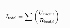
Acceptance Criterion:
Typical Example: In a DC 110 V circuit, simultaneously driving three protection device inputs (approximately 5,500 Ω per input) and one monitoring and control remote signaling input (approximately 2,200 Ω):

This is well below 5 A, so 5 A contacts are sufficient.
However, if five intermediate relay coils (approximately 110 Ω each) must be driven simultaneously:
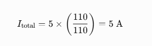
This reaches the rated current limit. For this application, select a model with 10 A contacts or install intermediate relays to increase the driving capacity.
Number of Contact Sets: At least two normally open (NO) contact sets per channel are required; three or more are recommended to accommodate protection device inputs, monitoring and control remote signaling inputs, and spare connections. Products with insufficient contact sets can cause difficulties during integrated commissioning of complex circuits.
五、How to Estimate the Required Number of Channels: Determine the Configuration Based on Testing Requirements
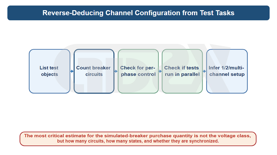
Illustration: Determining Channel Configuration Based on Testing Requirements
This is one of the most error-prone steps in procurement decisions. The number of channels should not be selected based on the voltage level, but rather on the number of circuit breakers involved in the protection configuration.
5.1 Estimation Steps
Step 1: Obtain the system-wide test plan or protection configuration list. Identify each protection type and the number of circuit breakers that must operate simultaneously during each test.
Step 2: Determine the maximum number of circuit breakers that must be controlled independently and simultaneously across all tests. This is the minimum number of channels required.
Step 3: Determine whether the channels require synchronized operation (busbar differential protection), asynchronous independent operation (automatic bus transfer), or independent phase-by-phase operation (single-phase auto-reclosing). Use these requirements to select the appropriate model.
5.2 Typical Application-Based Estimation Examples
Scenario 1: A county-level power supply company has the following annual system-wide testing requirements: 10 sets of 35 kV line protection (three-phase auto-reclosing), 5 sets of 110 kV line protection (single-phase auto-reclosing), 2 sets of 110 kV main transformer differential protection (two sides), and 1 automatic bus transfer system (ABT).
1.35 kV Line Protection: 1 channel (three-phase interlinked operation), with no independent phase control required.
2.110 kV Line Protection with Single-Phase Auto-Reclosing: 3 independent channels for phases A, B, and C.
3.Two-Side Main Transformer Differential Protection: 2 synchronized channels.
4.Automatic Bus Transfer (ABT): 2 independently operated, asynchronous channels.
The maximum requirement is three channels, with both independent phase-by-phase control and two-channel independent operation required. Conclusion: Select a model with four independent channels. Three channels can be used for phase-by-phase line protection testing, with one spare channel. This configuration also covers the two-channel requirements for automatic bus transfer and main transformer differential protection.
Scenario 2: A municipal-level commissioning team is responsible for system-wide busbar differential protection testing (six bus sections/bays) at 220 kV substations within its service area, as well as system-wide testing of all protection types.
1.Busbar Differential Protection (6 Bays): Requires 6 synchronized channels.
2.Other Protection Types: Require a maximum of 3 channels.
Conclusion: Select a dedicated multi-channel model with at least six channels. It must be a purpose-built multi-channel unit with a synchronization error of no more than 2 ms. Combining six single-channel units is not acceptable.
六、Basic, Dual-Channel, Multi-Channel, and Integrated Models: Application Boundaries
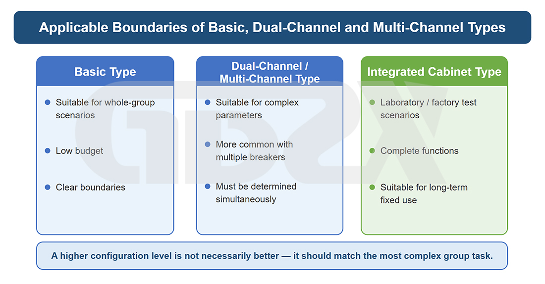
Illustration: Application Boundaries of Basic, Dual-Channel, and Multi-Channel Models
6.1 Basic Model (1–2 Channels, Fixed Settings)
Applicable Applications: Three-phase interlinked system-wide line protection testing, simple transformer differential protection (single-side trip verification), and protection training demonstrations.
Key Limitations:
1.Fixed time settings (e.g., 50/100/200 ms), with no fine adjustment and relatively large timing tolerances.
2.Typically lacks breaker failure / failure-to-operate simulation capability.
3.Not suitable for automatic bus transfer (requires two independent asynchronous channels) or single-phase auto-reclosing (requires independent phase control).
4.Measured timing accuracy is typically ±5 to ±10 ms, posing significant risks for time-sensitive protection functions.
When Not to Buy a Basic Model: If the test plan includes any of the following: breaker failure protection, busbar differential protection, or single-phase auto-reclosing.
Indicative Price: RMB 2,000–5,000 (tax included).
6.2 Standard Dual-Channel Model (2 Independent Channels, Continuously Adjustable)
Applicable Applications: Line protection testing (three-phase auto-reclosing), transformer differential protection (two-sided), automatic bus transfer system-wide testing, and dedicated breaker failure protection testing.
Key Specifications:
1.Continuously adjustable time settings with increments of ≤5 ms.
2.Measured timing accuracy of ±2 to ±5 ms.
3.Two independently controlled asynchronous channels.
4.Wide-range DC input voltage compatibility.
5.Breaker failure / failure-to-operate simulation capability.
Limitations: Does not support single-phase auto-reclosing, which requires three independently controlled phase channels. Not suitable for multi-bay synchronized busbar differential protection testing.
Indicative Price: RMB 5,000–12,000 (tax included).
6.3 Multi-Channel Model with Independent Phase Control (3–4 Channels, Independent A/B/C Control)
Applicable Applications: Line protection testing (including single-phase auto-reclosing), three-phase discrepancy protection, three-side transformer differential protection, and automatic bus transfer systems. Covers system-wide testing of all protection types at municipal-level power utilities.
Key Specifications:
1.Fully independent control of phase A, B, and C channels.
2.Continuously adjustable time settings in 1 ms increments.
3.Timing accuracy within ±2 ms.
4.Automatic DC input voltage recognition across the full supported range.
5.Breaker failure / failure-to-operate simulation capability.
6.10 A contact rating.
Limitations: Typically limited to a maximum of four channels, which is insufficient for system-wide busbar differential protection testing involving more than five bays.
Indicative Price: RMB 10,000–25,000 (tax included).
6.4 Dedicated Multi-Channel Synchronized Model (4 or More Channels, Precision Synchronization Control)
Applicable Applications: System-wide busbar differential protection testing (the primary application), integrated commissioning of large-scale control cabinets, and full-substation protection commissioning at high-voltage substations.
Key Specifications:
1.Number of channels ≥ the number of bays required for testing.
2.Measured multi-channel synchronization error ≤2 ms, supported by a test report.
3.Complete independent optocoupler isolation for each channel.
4.Full-range DC input voltage compatibility.
5.Breaker failure simulation capability.
6.Communication interfaces for coordinated control (RS485/Ethernet).
Key Procurement Principle: For this class of equipment, verified synchronization accuracy is more important than price. Require the manufacturer to provide measured timing waveforms demonstrating synchronized operation across six channels, rather than accepting a written assurance of “internal synchronization design.”
Indicative Price: RMB 20,000–80,000 (tax included, depending on channel count and functional configuration).
6.5 Integrated Laboratory-Grade Cabinet System
Applicable Applications: Testing and research institutes, factory acceptance testing of protection devices, training centers, and comprehensive commissioning of large-scale infrastructure projects.
Key Specifications: Building on the dedicated multi-channel synchronized model, additional features include:
1. Built-in multi-range DC power supply outputs.
2. 2.Comprehensive host computer software for test sequence programming, data logging, and report generation.
3.Optional solid-state relays with switching times of less than 1 ms.
4.Optional GOOSE communication support.
Indicative Price: RMB 40,000–100,000 or more (tax included).


