


NEWSnews
Simulated Circuit Breaker: Selection, Pitfalls & Supplier Evaluation
七、Recommendations for Common Procurement Scenarios
Scenario A: First-Time Purchase by a County-Level Power Supply Company’s Maintenance Team
Task Characteristics: Primarily annual routine protection system tests (line protection and main transformer differential protection), with occasional automatic bus transfer tests. No dedicated circuit breaker failure protection testing. Limited budget and moderate staff experience.
Recommended Configuration:
1.Channels: 2 independent channels, supporting individual phase control (A/B/C independently controllable)
2.DC Input: DC 85–265 V, with automatic wide-range voltage recognition
3.Timing: Continuously adjustable, 5 ms increments, with a measured accuracy of ±5 ms
4.Functions: Circuit breaker failure simulation (not a core requirement, but useful for future needs); three resistance settings (500 Ω / 1,000 Ω / 2,000 Ω)
5.Form Factor: Portable, weighing ≤5 kg
Avoid: Basic models with fixed time settings; single-voltage models supporting only DC 110 V.
Budget: RMB 6,000–10,000
Scenario B: Prefecture-Level Relay Protection Team — Replacing or Adding Test Equipment
Task Characteristics: Full-range protection system testing, including single-phase auto-reclosing, automatic bus transfer, three-side transformer protection, and circuit breaker failure protection. Occasionally undertakes 220 kV busbar differential protection testing, typically involving no more than six bays. Staff have strong technical skills.
Recommended Configuration:
1.Channels: 4 independent channels, with independent A/B/C phase control
2.DC Input: DC 48–264 V full-range input with automatic voltage recognition
3.Timing: Continuously adjustable in 1 ms increments, with measured accuracy of ±2 ms and a test report
4.Functions: Circuit breaker failure/trip failure simulation (mandatory); 10 A contacts; at least 3 contact groups per channel; RS485 communication interface
5.Multi-Channel Synchronization: Measured inter-channel timing deviation ≤2 ms, with a test report
6.Form Factor: Portable, weighing ≤10 kg, with a carrying handle
Budget: RMB 15,000–25,000.
Additional Recommendation: If 220 kV busbar differential protection system testing is performed frequently, consider selecting a 6-channel model directly to avoid additional purchases in the future.
Scenario C: Provincial Testing Institute or Large-Scale Infrastructure Commissioning Team
Task Characteristics: Full-range protection system testing, including busbar differential protection at ultra-high-voltage substations with more than eight bays. Requires batch commissioning, data archiving, automated integration with test platforms, and high accuracy.
Recommended Configuration:
1.Channels: 6–8 channels, expandable
2.DC Input: DC 24–264 V, with independent isolation for each channel
3.Timing: 1 ms increments, with measured accuracy of ±1 ms and a traceability report
4.Contacts: Optional solid-state relays (switching time
Budget: RMB 50,000–100,000.
Scenario D: Factory Acceptance Testing at Protection Device Manufacturers
Task Characteristics: Frequent testing of various protection device models, requiring diverse parameter configurations and rapid switching. High data archiving requirements and long-term, high-frequency operation.
Recommended Configuration: Based on Scenario C, focus on the following: contact life of at least 1 million operations (or select solid-state relays); PC software that supports saving and recalling parameter templates to reduce repetitive setup time; and reliable technical support and spare parts supply from the manufacturer.
八、Common Pitfalls in Procurement
Pitfall 1: Confusing Setting Resolution with Measured Accuracy
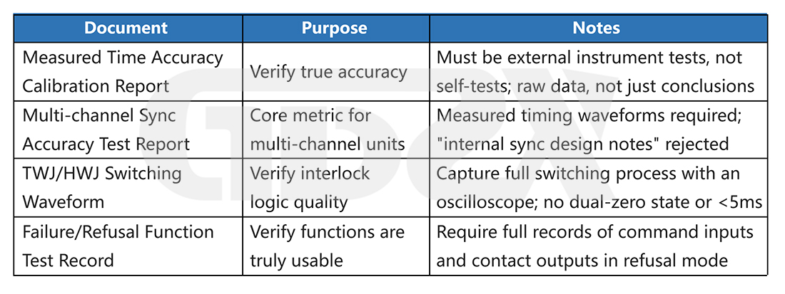
The manufacturer's technical specification states “operating time adjustment accuracy: ±1 ms.” This may mean that the setting resolution is 1 ms, while the actual operating time can deviate from the set value by ±10 ms. These are two different concepts; the latter is what really matters in protection system testing. Ask the manufacturer for an actual measurement and calibration report. If none is available, then no such report exists.
Pitfall 2: Combining Multiple Single-Channel Units Instead of Using a Multi-Channel Model
This is one of the most common procurement mistakes in busbar differential protection system testing. The usual justification is that “four single-channel units cost less than one four-channel unit.” Although the required number of channels appears to be sufficient, the timing of the individual units cannot be properly synchronized, and deviations may reach tens of milliseconds. As a result, the timing data from the entire test has no engineering value.
The higher cost of dedicated multi-channel models is largely due to their precision internal synchronization control circuits. This is not a cost that can be eliminated without consequence; it is a fundamental capability required for multi-channel synchronized testing.
Pitfall 3: Overlooking the Quality of TWJ/HWJ Mutual Interlocking Logic
During switching, low-end devices may have a brief double-zero interval (TWJ and HWJ are both 0). If this interval exceeds the protection device's alarm detection time (typically 5–10 ms), a “control circuit disconnection” alarm may be triggered. This generates a false alarm in the protection system test records and affects the interpretation of test results.
When purchasing, require the supplier to provide oscilloscope waveforms of TWJ/HWJ switching, rather than relying solely on a written assurance that “mutual interlocking protection is provided.”
Pitfall 4: Selecting the Number of Channels Based on Voltage Level Instead of Protection Configuration
“For 110 kV line protection, a single-channel unit is sufficient.” This statement is correct for three-phase auto-reclosing scenarios but incorrect for single-phase auto-reclosing scenarios. The required number of channels is determined by the circuit breaker control scheme specified in the protection configuration, not by the voltage level. Before purchasing, review the complete protection system test plan.
Pitfall 5: Purchasing a Device Without Trip Failure Simulation for Circuit Breaker Failure Protection Testing
This is one of the most disruptive procurement mistakes because the problem is usually discovered only after arriving on site. The core of circuit breaker failure protection system testing is trip failure simulation, a function that basic models simply do not provide. Before purchasing, check whether circuit breaker failure protection testing is included in the test list. If it is, trip failure simulation is mandatory, not optional.
Pitfall 6: Putting the Equipment into Service Without Acceptance Testing
Putting the device into service for protection system testing without first conducting a timing accuracy acceptance test can compromise the validity of all previous test data if the device fails to meet the required accuracy, potentially requiring all tests to be repeated.
Spending half an hour on three tests during delivery acceptance—timing accuracy testing, DC input range testing, and TWJ/HWJ waveform capture—can help identify most problematic products.
九、How to Evaluate Manufacturer Documentation, Logic Capabilities, and After-Sales Commitments
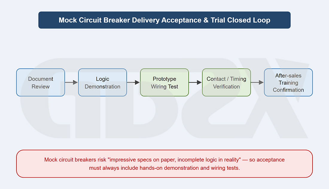
Illustration: Closed-Loop Process for Simulated Circuit Breaker Delivery Acceptance and Trial Use
9.1 Four Required Documents
9.2 On-Site Testing or Prototype Demonstration
When conditions permit, require the manufacturer to provide a prototype demonstration or on-site testing to verify the following three aspects:
Test 1: Measured Timing Accuracy. Trigger the device 10 times at each of three settings: 50 ms, 100 ms, and 200 ms. Record the actual operating times and calculate the repeatability error. Compare the results with the requirements specified in the tender documents.
Test 2: DC Input Operating Limits. Adjust the DC input voltage to 80% of the rated value to simulate low-voltage operating conditions, and verify whether the device continues to operate reliably. This can reveal design issues with the optocoupler triggering threshold.
Test 3: TWJ/HWJ Switching Waveform Capture. Use a logic analyzer or the digital input waveform recording function of a relay protection tester to record the complete switching process and check for any double-zero interval.
9.3 Key Points for Evaluating After-Sales Service Commitments
1.Calibration Services: Timing accuracy may drift over time and with changes in ambient temperature. Does the manufacturer provide periodic recalibration services?
2.Wear Parts Supply: Are the replacement intervals for relay contacts and the channels for obtaining spare parts clearly specified?
3.On-Site Support: Does the manufacturer provide on-site commissioning guidance during initial use?
4.Firmware Upgrades: Do communication protocols, system integration functions, and other features support future upgrades?


