


NEWSnews
Simulated Circuit Breaker: Overview, Applications & Working Principles
一、What Is a Simulated Circuit Breaker Device?
1.1 Basic Definition
The Simulated Circuit Breaker Unit (hereinafter referred to as the “simulated circuit breaker” or “SBU”) is a dedicated test device used in complete-set relay protection testing to simulate the opening and closing operations of an actual circuit breaker, changes in position status, and output of auxiliary contact signals.
Its sole purpose is to provide a complete set of feedback signals indicating that the circuit breaker has operated in a controlled, repeatable, and precisely timed manner at the moment the relay protection test set injects fault quantities and the protection device issues trip or closing commands. These signals include open/closed position contact switching, opening and closing of auxiliary contacts, and responses of the trip and closing circuits. This enables the protection device and the entire secondary circuit to recognize that the actual on-site circuit breaker has operated, thereby completing the full operating logic cycle.
Concepts That Are Easily Confused: A simulated circuit breaker unit is not a relay protection test set, a contact conversion box, or a DC power supply. It is an independent device specifically designed to simulate circuit breaker behavior and serves as the “controlled object” in the complete-set relay protection test circuit. The relay protection test set provides fault currents and voltages, the protection device issues trip and closing commands, and the simulated circuit breaker receives these commands and provides feedback on circuit breaker operation. Together, the three form a complete relay protection test circuit.
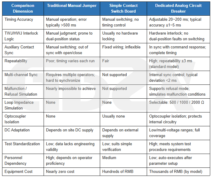
1.2 Key Differences from Traditional Manual Jumper Simulation
1.3 Position of the Device in the Complete Relay Protection Test Circuit
Standard Complete-Set Relay Protection Test Signal Sequence: The relay protection test set outputs simulated fault quantities → The protection device detects the fault quantities and makes a decision → The protection device issues trip/closing commands → The simulated circuit breaker receives the commands → The open/closed position contacts switch and auxiliary contact signals are output → The protection device reads back the position signals to complete the operating logic cycle → The relay protection test set records the operating time and waveforms.
The simulated circuit breaker serves as a substitute for the actual circuit breaker in the above circuit, enabling the complete operating logic cycle to be executed even in a testing and commissioning environment where no actual circuit breaker is present.
二、Why It Is Essential for Complete-Set Relay Protection Testing
2.1 Essential Requirements of Complete-Set Relay Protection Testing
Complete-set relay protection testing verifies the entire operating logic, timing sequence, and input/output behavior of the protection device in accordance with applicable relay protection testing regulations and standards. The current valid editions of the relevant standards should be followed, including GB/T 14285, DL/T 995, and DL/T 623.
Complete-set testing requires that the protection device operate within a complete secondary circuit environment; trip and closing commands receive responses from an actual or simulated “controlled object,” with correct position feedback; auxiliary contact states strictly correspond to the circuit breaker’s open/closed positions; operating sequences remain within the specified tolerances; and multiple circuit breakers can be simulated independently or in coordination.
2.2 Practical Challenges Without a Simulated Circuit Breaker
Distorted Timing Verification. Manual contact switching cannot control the exact switching time, making the recorded operating times invalid for engineering purposes.
Confused Position Feedback. Delayed or incorrectly sequenced manual switching between open and closed positions can disrupt protection logic, leading to maloperation or incorrect judgments of failure to operate.
Multi-Channel Synchronization Cannot Be Achieved. Busbar differential protection, automatic bus transfer, and other protection functions require multiple circuit breakers to operate simultaneously or in a specified sequence. Without dedicated equipment, these conditions cannot be simulated.
Breaker Failure and Failure-to-Operate Conditions Cannot Be Reproduced. The core of breaker failure protection testing is to verify protection behavior when the circuit breaker fails to operate. Without dedicated equipment, these conditions cannot be reliably reproduced.
Unreliable Test Data. Data obtained through manual operation lacks engineering validity and cannot meet acceptance testing requirements.
2.3 Roles and Coordination of the Simulated Circuit Breaker and Relay Protection Test Set
The relay protection test set serves as the “fault source” and “measuring instrument,” while the simulated circuit breaker acts as a “substitute for the controlled device.” Both are indispensable: the relay protection test set enables the protection device to “detect a fault,” while the simulated circuit breaker enables it to “complete the operating logic.” Complete-set testing requires the coordinated operation of both devices to fully verify the protection device’s end-to-end behavior, from fault detection to circuit breaker operation feedback.
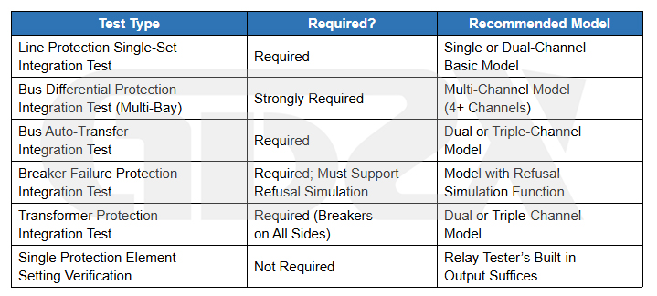
2.4 Which Tests Require a Simulated Circuit Breaker and Which Can Be Simplified
三、Working Principle: Signal Simulation Logic Explained
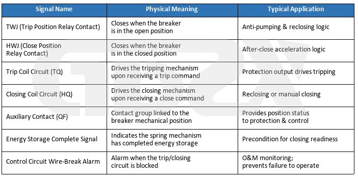
3.1 Signal System of an Actual Circuit Breaker
3.2 How the Simulated Circuit Breaker Reproduces These Signals
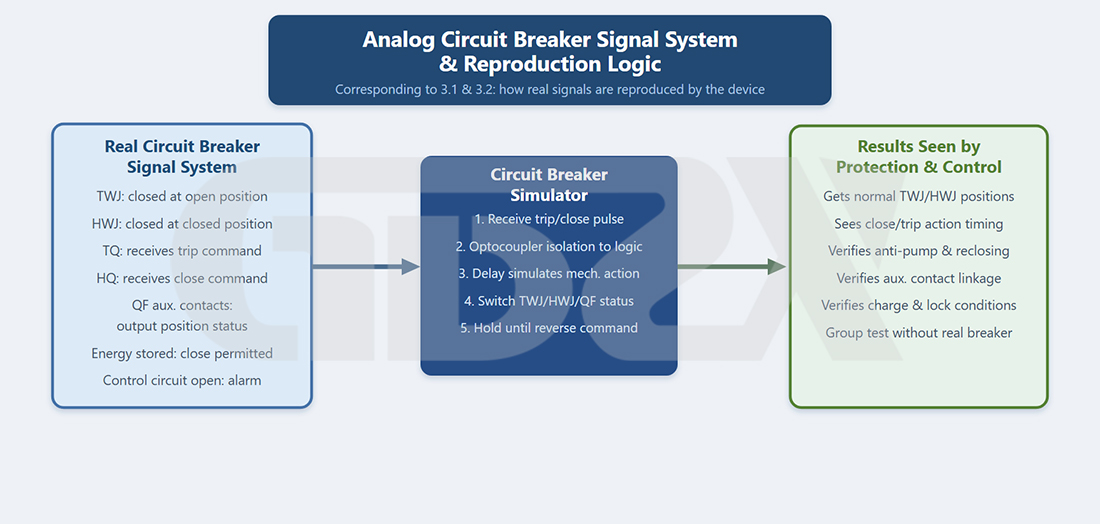
Figure 3-1 Signal System and Reproduction Logic of the Simulated Circuit Breaker
The Operating Process Consists of Four Steps:
1. Trip/Closing Command Reception: The trip/closing command issued by the protection device enters the unit as a DC voltage pulse. The optocoupler isolation circuit converts the high-voltage electrical signal into a low-voltage logic signal.
2. Time Delay Processing: The microcontroller applies a delay based on the preset opening and closing time parameters to simulate the mechanical operating time of an actual circuit breaker.
3. Contact Switching: After the delay expires, the relay group is driven to switch states. TWJ and HWJ exchange states, and the auxiliary contact groups switch synchronously.
4. State Retention and Reset: The new position state is maintained until a reverse command is received or a manual reset is performed.
3.3 Mutual-Exclusion Logic Between TWJ and HWJ
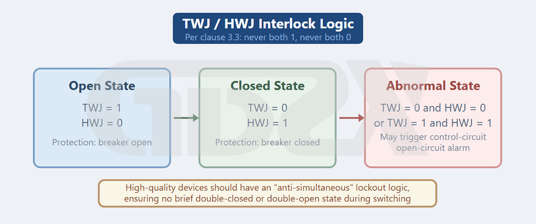
Figure 3-2 Schematic Diagram of TWJ–HWJ Mutual-Exclusion Logic
TWJ and HWJ should never be 1 simultaneously, nor should they both be 0 (the latter triggers a “control circuit disconnection” alarm). High-quality devices incorporate dedicated interlocking logic to prevent these simultaneous states, ensuring that neither a transient dual-ON state nor a dual-zero state occurs during switching.
Note: If a simulated circuit breaker briefly enters a dual-zero or dual-one state during TWJ/HWJ switching, the protection device may trigger a “control circuit disconnection” alarm, interfering with complete-set relay protection test results. This is one of the important criteria for evaluating the quality of a simulated circuit breaker.
3.4 Auxiliary Contact Capacity and Configuration Requirements
When selecting a simulated circuit breaker, pay attention to the contact rating (AC/DC rated current, such as 5 A or 10 A), contact type (normally open, NO / normally closed, NC), number of contact groups, and contact switching time. When connecting external high-current loads, ensure that the rated limits are never exceeded. Verify the specific parameters against the device manual and the requirements of the on-site circuit.
3.5 DC Voltage Adaptation Principle
The common DC control voltages are DC 48 V, DC 110 V, and DC 220 V. Single-voltage models support only one voltage level, while mid- to high-end devices use wide-range optocoupler inputs or multi-range switching to support multiple voltage levels. Before purchasing, be sure to confirm the on-site DC control voltage and verify that it matches the device specifications.
3.6 Purpose of Circuit Resistance Settings
Circuit resistance settings (e.g., 500 Ω, 1000 Ω, and 2000 Ω) are used to simulate the circuit impedance characteristics of actual circuit breaker trip and closing coils, ensuring that the trip/closing circuit supervision circuits of the protection device operate within their normal operating ranges. The specific resistance configuration should be confirmed based on the manual of the protection device under test and the technical parameters of the on-site circuit breaker.


