


NEWSnews
Simulated Circuit Breaker: Selection, FAQs & Field Application Guide
十、Procurement, Selection & Specification Analysis
Consultant’s Perspective: After 20 years of experience in protection system testing and equipment procurement, I have found that the biggest procurement pitfalls are not buying equipment with excessive specifications, but purchasing low-cost products with ambiguous parameters. On-site, these products may turn out to be incompatible with DC 110 V, or the device may lack a trip-rejection mode when breaker-failure protection testing is required. This chapter skips the “typical ranges” and provides three practical procurement configuration lists, along with verification criteria for each parameter.
10.1 Five Essential Checks Before Selection
Before contacting any manufacturer, verify the following five on-site parameters. Missing even one could result in a wasted trip.
Check 1: DC Control Voltage. Check the design drawings or the nameplate of the DC panel. Do not guess based on experience. DC 110 V is the primary control voltage in 110 kV substations, but older substations undergoing renovation and some communication DC systems use DC 48 V. Substations rated 500 kV and above may use DC 220 V. If a device that supports only DC 110 V is connected to a DC 220 V supply on-site, its optocouplers may be destroyed by overvoltage. I have seen this happen more than once.
Check 2: Circuit Breaker Trip/Close Coil Resistance. Check the circuit breaker nameplate or factory manual. The unit is Ω. Typical ranges are as follows: trip coils in spring-operated circuit breakers are usually 100–300 Ω; coils in hydraulic or pneumatic mechanisms may have lower resistance (50–150 Ω); and coils in older circuit breakers may exceed 500 Ω. This parameter determines the resistance setting you need and whether you must account for control-circuit disconnection alarms.
Check 3: Number of Circuit Breakers Involved in the Test. One channel is sufficient for a single-set protection test on a transmission line. Automatic bus transfer (ABT) testing requires two channels. Three-winding transformer differential protection requires three channels. For busbar differential protection, calculate the required number of channels based on the number of bays. Five bays require five channels. There is no room for compromise here.
Check 4: Does the Test Plan Include Circuit Breaker Failure Protection? If it does, the device must support a no-trip (trip-rejection) mode. This is a mandatory requirement. Basic models do not provide this function, and it is not negotiable.
Check 5: Where Will the Device Primarily Be Used in the Future? If the device will remain at a single substation, a model rated for the site's specific DC control voltage is sufficient. For mobile testing teams working across multiple substations, a wide-range DC input (DC 48–264 V) is essential. It eliminates the need to verify the DC voltage at every site and reduces the risk of damaging the device through incorrect connections.
10.2 Three Specific Procurement Configurations
The following configurations represent the recommended minimum acceptable specifications, not brand recommendations. These parameters can be incorporated directly into the technical specifications for tendering.
Configuration A: Routine Protection System Testing for County-Level Maintenance Teams and Primary Substations
Applicable Scenarios: Primarily used for full-group testing of 110 kV line protection and main transformer differential protection, with occasional automatic bus transfer (ABT) testing. Not intended for dedicated circuit breaker failure protection testing. Budget is limited.
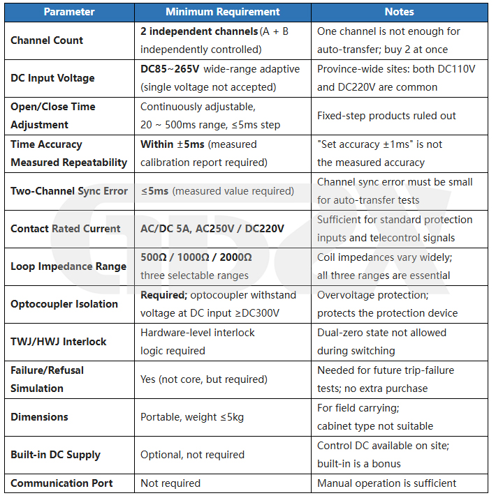
Reference Procurement Budget: A two-channel portable device meeting the above specifications typically costs approximately RMB 14,000–18,000 (tax included). For products priced below RMB 14,000, carefully verify the measured time-accuracy values and confirm that TWJ/HWJ mutual-exclusion logic is genuinely supported.
In One Sentence: Configuration A is qualified if it meets all five requirements: two channels, wide-range DC input, continuously adjustable timing, circuit breaker failure functionality, and three resistance settings.
Configuration B: Prefecture-Level Commissioning Teams / Comprehensive Coverage of Multiple Protection Types
Applicable Scenarios: Responsible for full-group testing of all types of protection within the service area, including line protection (single-phase autoreclosing), busbar differential protection (up to six bays), automatic bus transfer (ABT), transformer protection, and circuit breaker failure protection. Primarily intended for mobile field operations.
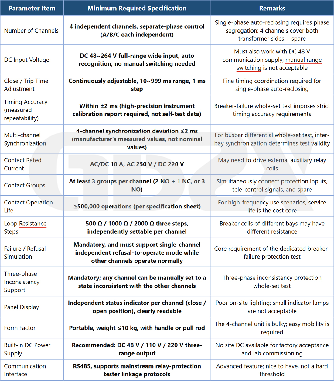
Reference Procurement Budget: A portable device with four independently controlled phase channels that meets the above specifications typically costs approximately RMB 22,000–35,000 (tax included). For products priced above RMB 35,000, carefully verify the justification for the price premium. For products priced below RMB 22,000, pay particular attention to measured four-channel synchronization accuracy.
In One Sentence: Four independently controlled phase channels, automatic identification across the full DC voltage range, ±2 ms accuracy, 10 A contacts, and comprehensive circuit breaker failure functionality are the key requirements for Configuration B.
Configuration C: Provincial Testing Institutes, Infrastructure Commissioning Teams, and Laboratories
Applicable Scenarios: Full-substation integrated commissioning for substations rated 220 kV and above, comprehensive protection system commissioning for major infrastructure projects, factory acceptance testing, and protection device performance research. High test data quality is required, along with integration with test platforms.
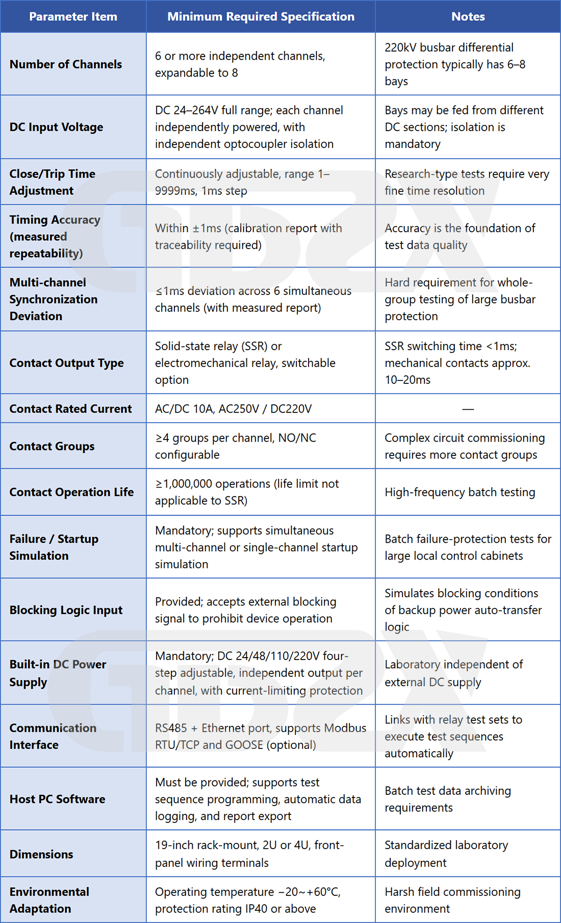
Reference Procurement Budget: A six-channel rack-mounted device with the above specifications, including host computer software, typically costs approximately RMB 40,000–80,000 (tax included). For products priced above RMB 80,000, verify whether the premium features are genuinely necessary. For Configuration C, reducing specifications to save costs is not recommended, as accuracy and synchronization are the core value drivers in this application.
In One Sentence: Six or more channels, ±1 ms accuracy, independently isolated DC supplies for each channel, optional solid-state relays, comprehensive communication and integration capabilities, and host computer software constitute the baseline requirements for Configuration C.
10.3 Key Technical Requirements for Tender Specifications
After purchasing dozens of devices, I have found that the timing accuracy requirement is the clause manufacturers are most likely to exploit in tender documents. The tender specifications must be worded as follows, rather than simply stating “open/close timing accuracy: ±X ms”:
Timing Accuracy Requirements: The measured repeatability error of opening and closing operating times (defined as half the difference between the maximum and minimum values from 10 consecutive measurements at the same setting) shall not exceed ±X ms. The supplier shall provide an actual measurement and calibration report obtained using a timing instrument with a resolution of at least 0.1 ms. The report shall include 10 measurement results at each of at least five different time settings. The manufacturer's stated setting accuracy shall not be considered sufficient to meet this requirement.
Multi-Channel Synchronization Error:
Multi-Channel Synchronization Accuracy Requirements: When multiple channels are triggered simultaneously, the difference between the actual operating times of any two channels (defined as the absolute difference between their measured operating times) shall not exceed X ms. An actual measurement report must be provided. Descriptive claims such as “internal clock synchronization” or “software synchronization” alone shall not be accepted as evidence of compliance.
10.4 Three Essential Tests During Acceptance Testing
After the equipment arrives, do not rush to connect the wiring and begin testing. Spend half an hour performing these three tests to identify approximately 60% of problematic products:
Test 1: Actual Timing Accuracy Verification. Connect a relay protection tester (or a high-precision time recorder) to the device's trip input. Trigger the device 10 times at each of three different time settings, such as 50 ms, 100 ms, and 200 ms, and record the actual operating time for each measurement. For each group, subtract the minimum value from the maximum value and divide the result by two to obtain the measured repeatability error. Compare the results against the tender requirements. If the results exceed the specified limits, require corrective action or return the product.
Test 2: DC Input Voltage Range Verification. Adjust the DC input voltage to 80% and 110% of the rated value, respectively, and verify that the device continues to operate reliably. This test can reveal poorly designed optocoupler triggering thresholds. If the optocoupler trigger current is insufficient, a reduced input voltage may cause intermittent failures to operate.
Test 3: Capture and Analyze TWJ/HWJ Switching Waveforms. Use a logic analyzer or the digital-input waveform recording function of a relay protection tester to record a complete circuit breaker opening operation. Observe the switching waveforms as TWJ transitions from 0 to 1 and HWJ transitions from 1 to 0. Confirm that no double-zero state occurs during the transition, meaning there is no time interval in which TWJ and HWJ are simultaneously at 0. A double-zero interval exceeding 5 ms may trigger a control-circuit disconnection alarm in the protection device, disrupting the normal execution of the full-group test.
10.5 Operating Life and Routine Maintenance
Relay contacts are the primary wear components. Their typical service life is specified in the number of operating cycles; refer to the product specifications. Assuming a prefecture-level commissioning team performs approximately 500 full-group tests annually, with an average of 20 opening and closing operations per test, mechanical contacts rated for 200,000 operations would last approximately 20 years, while those rated for 100,000 operations would last approximately 10 years. Actual service life depends on the contact load current; higher loads accelerate deterioration.
Signs that the contacts are approaching the end of their service life:
1.Switching times begin to increase and become unstable.
2.Contact resistance rises from the factory value of less than 50 mΩ to more than 200 mΩ.
3.Intermittent failure to operate or contact sticking occurs.
It is recommended to measure the contact resistance of each channel annually using a multimeter. Replace abnormal contacts or return the device to the manufacturer for repair promptly. Do not wait until a failure occurs at the test site.
10.6 Final Recommendations from an Experienced Consultant
I have seen too many organizations cut prices to meet budget constraints, only to end up purchasing products with overstated timing accuracy and unreliable DC input compatibility. These products then cause various on-site problems, ultimately costing more in troubleshooting travel expenses and lost time. The simulated circuit breaker unit is a critical component in the full-group testing circuit. If its data is unreliable, the conclusions of the entire test cannot be trusted.
It is better to purchase fewer accessories than to compromise on the accuracy and reliability of the main unit.
Practical Recommendation: After receiving a manufacturer's quotation, request the following:
1.An actual timing accuracy calibration report (nominal specifications alone are not acceptable).
2.An actual multi-channel synchronization accuracy test report (for multi-channel models).
3.At least three genuine customer case studies involving the same types of testing scenarios.
Manufacturers able to provide all three items are generally more likely to offer products of acceptable quality.
十一、Frequently Asked Questions: Categorized Answers
Standards-Related Questions
Q: Which standard should be used as a reference for operating time tolerances in full-group testing?
The currently effective relay protection testing regulations shall be followed. Tolerance requirements vary depending on the type of protection. Regulations such as DL/T 995 are commonly referenced, but the specific values must be confirmed against both the manual of the protection device under test and the applicable edition of the regulations governing the project. This article does not specify numerical values to avoid providing misleading information if the regulations are updated.
Q: Is there a dedicated product standard for simulated circuit breaker units?
Currently, there is no dedicated national or industry standard specifically governing these devices. During procurement, priority should be given to ensuring that the device meets the technical requirements of the protection equipment under test, rather than pursuing certification to standards for the device itself.
Operating Principle Questions
Q: What applications correspond to the 500 Ω, 1,000 Ω, and 2,000 Ω circuit resistance settings?
The 500 Ω setting is suitable for circuit breakers with relatively low coil resistance. The 1,000 Ω setting is a general-purpose intermediate setting suitable for most circuit breakers rated 110 kV and above. The 2,000 Ω setting is suitable for circuit breakers with relatively high coil resistance. Refer to the circuit breaker nameplate or manual to determine the coil resistance and select the closest matching setting.
Q: Is a time adjustment resolution of 1 ms sufficient?
For most relay protection full-group tests, a time adjustment resolution of 1 ms is sufficient. Greater attention should be paid to the deviation between the actual operating time and the set value, particularly repeatability, as this is a more meaningful indicator of equipment quality than adjustment resolution alone.
Operational Questions
Q: Three-phase simultaneous operation works normally, but independent single-phase operation fails. What should be done?
First, confirm whether the device supports independent phase control. If it does, check that the phase-control wiring is independent, verify that the operating mode has been switched to “Independent Phase Control,” and inspect the DC polarity and connection integrity of the single-phase input terminals.
Q: What should be done if an auxiliary contact sticks and cannot be reset?
For minor sticking, try applying a reverse drive signal to force a reset, provided this procedure is supported by the manufacturer's instructions. Severe sticking requires replacement of the internal relay. Also, recheck whether the external load current and operating frequency exceed the device's rated capabilities.
Safety-Related Questions
Q: What are the consequences of reversing the DC polarity during full-group testing?
In mild cases, the optocoupler may fail to trigger, leaving the device unresponsive. In more severe cases, the internal optocoupler circuit or input protection components may be damaged or burned out. Always use a multimeter to verify polarity before applying power.
Q: What safety precautions should be observed when wiring a simulated circuit breaker during on-site full-group testing?
Before wiring, confirm that both the device and the on-site equipment are de-energized. Verify the DC polarity before making connections. Wire the trip/close circuits separately from the remote signaling/digital input circuits. After completing the wiring, perform an initial no-load verification. Never perform wiring operations on energized circuits during full-group testing.
Selection-Related Questions
Q: How should users choose between models compatible with DC 48 V, 110 V, and 220 V and single-voltage models?
For users operating at a single substation where the DC voltage is known and fixed, a single-voltage model is sufficient. For mobile testing teams working across different substations, a wide-range, multi-voltage-compatible model offers better value for money and reduces the risk of DC voltage incompatibility.
Q: Do 10 kV, 110 kV, and 220 kV projects all require multi-phase simulated circuit breakers?
No. The deciding factor is the protection configuration. In 10 kV systems without independent phase tripping requirements, a three-phase simultaneous-operation model is sufficient. Line protection at 110 kV and above typically includes independent phase tripping and single-phase autoreclosing functions, requiring a model with three independently controlled phase channels. The selection should be based on the protection configuration, not solely on the voltage level.
Common Misconceptions
Q: Does purchasing a simulated circuit breaker unit guarantee successful completion of a full-group protection test?
Not necessarily. A simulated circuit breaker only addresses the stage of simulating circuit breaker operations. Successful completion of a full-group protection test also depends on the correct configuration of the relay protection tester, proper setting of protection parameters, correct secondary circuit wiring, and the test personnel’s understanding of the full-group testing logic. The key difference is not whether the device can simulate opening and closing operations, but whether it can reliably reproduce complex protection scenarios and enable the correct interpretation of test results.
Q: Can a simulated circuit breaker unit replace a real circuit breaker in primary-secondary linkage operation tests?
No. Primary-secondary linkage operation tests require a real circuit breaker to verify whether protection trip commands can actually actuate the circuit breaker mechanism and whether the breaker can interrupt current in the primary circuit. A simulated circuit breaker can only simulate secondary-side signal behavior and cannot replace verification of the real circuit breaker’s mechanical operation or primary electrical performance.
十二、Summary and Field Use Recommendations
12.1 Understanding Simulated Circuit Breaker Units Correctly
A simulated circuit breaker unit is a standardized substitute for the “controlled end” of a full-group testing circuit. It is a key auxiliary device that enables protection operation logic to complete the full testing sequence without a real circuit breaker. The core criteria for evaluating a unit are whether its timing accuracy is stable and repeatable, whether its TWJ/HWJ switching logic is rigorous and free of anomalies, whether its wiring compatibility meets on-site requirements, and whether it can reliably simulate special conditions such as breaker failure and failure to operate.
12.2 Procurement Recommendations Summary
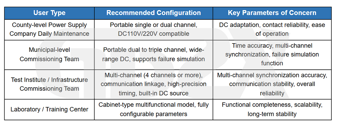
Key Selection Criterion: Not every project requires the highest-specification model. The key is to match the device to the complexity of the test tasks, circuit requirements, personnel capabilities, and budget.
12.3 Summary of Field Use Recommendations
Three Checks Before Wiring: Confirm that the control DC voltage level matches the device specifications; ensure that DC polarity is clearly marked and verified; confirm that the function of each channel has been defined and labeled.
Three Verifications After Power-On: Check that the panel indicators are operating normally; verify that TWJ/HWJ and auxiliary contacts switch correctly during manual opening and closing operations; use a multimeter to check the output terminals and confirm that the signals are correct.
Three Checks Before Full-Group Testing: Ensure that the timing settings match the test plan; verify that the initial position status is correct; complete an open-circuit functional check of the interface with the relay protection tester.
Three Records to Keep During Testing: Record the simulated circuit breaker’s opening and closing time settings; record the actual operating time measured during each test for correcting full-group test timing data; document any abnormal conditions and the actions taken to resolve them.
Three Maintenance Precautions: Regularly inspect terminal connections, clean them, and tighten them as necessary; do not operate auxiliary contacts beyond their rated current; when the device is not in use for extended periods, store it in a dry, dust-free environment and perform periodic power-on self-checks.


