


NEWSnews
Simulated Circuit Breaker: Selection Comparison, Application Guidelines & Standa
十三、Comparative Model Selection Analysis
This chapter compares five dimensions under the same test tasks and site conditions, using protection relay integrated testing scenarios as the sole reference for its conclusions. The objective is to help readers make model selection decisions that match actual project requirements, rather than promote the highest-specification model.
13.1 Comparison 1: Simulated Circuit Breaker Unit vs. Traditional Manual Jumper Simulation
Comparison Conditions: The same line protection integrated test, a single circuit breaker, and equivalent test personnel competency.
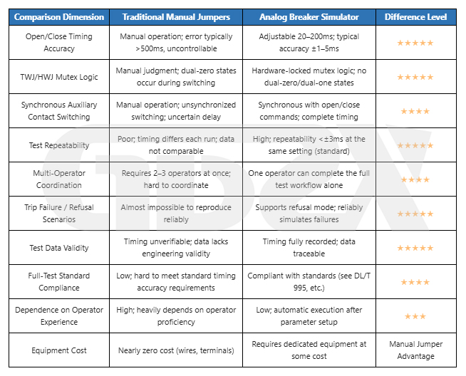
Core Advantages of a Simulated Circuit Breaker Unit: Timing changes from “uncontrollable” to “controllable.” Hardware ensures TWJ/HWJ mutual exclusion and auxiliary contact synchronization logic. One person can complete the entire procedure, and the integrated test timing data are valid for engineering purposes.
Scenarios Where Manual Jumper Simulation Remains Useful: Temporary, one-time wiring verification (when timing data are not required); basic verification of protection device inputs and outputs (when timing accuracy is not required); and auxiliary use in equipment failure emergencies.
13.2 Comparison 2: Simulated Circuit Breaker Unit vs. Simple Contact Switching Board
Comparison Conditions: A contact switching board is defined as a simple device with TWJ/HWJ contact outputs and manual switching between open and closed positions, without automatic timing control.
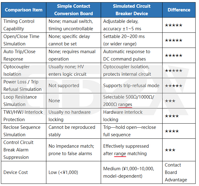
Fundamental Difference: A contact switching board addresses whether contact outputs are available, whereas a simulated circuit breaker ensures that contacts switch at the correct time according to the correct logic. In integrated protection testing, this difference has a decisive impact on the validity of test results.
Scenarios Where a Contact Switching Board Remains Suitable: Verifying that a protection device correctly recognizes open/closed status inputs (with no timing requirements); rapid functional checks during pre-wiring; training demonstrations and educational purposes; and use under strict budget constraints, provided its limitations are clearly understood.
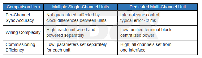
13.3 Comparison 3: Single-Channel vs. Dual-/Multi-Channel Models
Comparison Conditions: Models from the same product line, differing only in the number of channels and synchronization control capabilities.
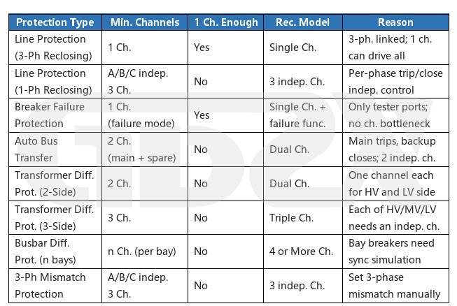
The core value of multi-channel models lies not in the number of channels itself, but in multi-channel synchronization accuracy. The fundamental problem with combining multiple single-channel units is that their timing cannot be synchronized. During integrated busbar differential protection testing, the operating time differences between bays may exceed the permissible tolerance specified in the applicable regulations, invalidating the test results.
13.4 Comparison 4: Single-Voltage vs. Multi-Voltage Compatible Models
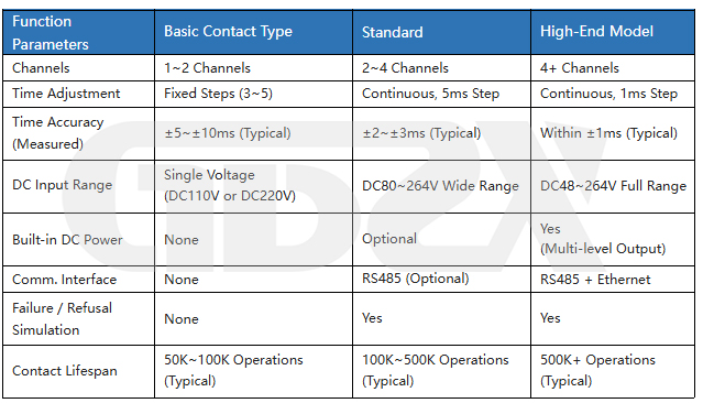
Selection Recommendation: Before purchasing, confirm the distribution of DC voltage levels across the substations served by your organization. If projects involve both DC 110 V and DC 220 V, a multi-voltage compatible model is a more cost-effective long-term investment. If the operating environment is exclusively DC 110 V, a single-voltage model is sufficient.
13.5 Comparison 5: Basic Contact-Type vs. Advanced Models
Practical Limits of Advanced Features: Circuit breaker failure / refusal-to-trip simulation is the key feature distinguishing basic from standard models and is essential for integrated circuit breaker failure protection testing. A 1 ms timing step is primarily intended for dedicated three-phase discrepancy protection tests and high-quality data recording at testing institutes; it is not a basic requirement for routine maintenance teams. Communication and automated coordination are valuable for frequent, batch testing, whereas manual operation is generally sufficient for routine maintenance at a single substation.
Scenarios Where Basic Models Are a Reasonable Choice: Routine maintenance by county-level power supply companies and primary substations; testing primarily focused on line protection, without dedicated circuit breaker failure protection tests; strict budget constraints; and teams with limited experience operating complex equipment.
⚠️ Limitation Notice: If a basic model is used for integrated circuit breaker failure protection testing, the test results will be incomplete due to the lack of a failure-to-trip simulation function. Before purchasing, confirm whether circuit breaker failure protection testing is included in the test plan.
十四、Model Selection Boundaries and Applicability Principles
14.1 Not Every Project Requires an Advanced Model
The three key features of advanced models—circuit breaker failure simulation, 1 ms timing accuracy, and communication-based coordination—are unnecessary for most routine integrated line protection tests. For county-level maintenance teams, annual routine integrated tests primarily focus on line protection, and standard or even basic models can meet the applicable regulatory requirements. For these teams, advanced models represent an unnecessary cost rather than an improvement in test quality.
Advanced models are genuinely needed in the following scenarios: dedicated circuit breaker failure protection tests (failure simulation is essential); integrated busbar differential protection tests (multi-channel synchronization is essential); and high-frequency batch commissioning (communication-based coordination improves efficiency).
14.2 Not All Protection Tests Require Multi-Phase Simulation
Whether three independent phase channels are required depends on the protection configuration, not the voltage level:
1.Three-phase linked protection (three-phase overcurrent, three-phase differential protection, etc.): Three outputs can operate synchronously. A single-channel model with three-phase linked control is sufficient; independent three-phase control is unnecessary.
2.Phase-segregated tripping protection (single-phase reclosing on transmission lines): Three independent phase channels are essential.
3.Busbar differential protection: One channel is required per bay. The number of channels depends on the number of bays and is not directly related to independent three-phase control.
Configuring three independent phase channels unnecessarily for three-phase linked protection results in avoidable costs.
14.3 Not Every Site Is Suited to the Most Complex Equipment
The more complex the equipment, the greater the demands on operators. If operators are unfamiliar with protocol configuration, communication-enabled models may introduce additional troubleshooting challenges during commissioning. For less experienced personnel at primary-level maintenance teams, entry-level and mid-range models with straightforward functions and intuitive operation can often complete tests more reliably than advanced models.
14.4 Four Key Principles for Matching Model Selection to Requirements
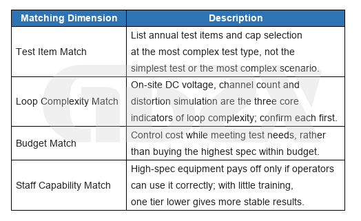
14.5 Summary of Engineering Considerations
The value of a simulated circuit breaker unit in integrated protection relay testing is tangible. It upgrades traditional testing methods characterized by “uncontrolled timing, unguaranteed logic, and unreliable data” into a standardized testing process featuring “precise timing, complete logic, and traceable data.” This is its fundamental advantage over manual jumper simulation and simple contact switching boards, and the primary reason for purchasing one.
However, the limits of these advantages are clear: it simulates the secondary electrical behavior of a circuit breaker but cannot replace its mechanical operation or primary electrical performance. It improves the standardization and efficiency of integrated testing but cannot replace the operator’s understanding of the test logic. It addresses the need for a substitute controlled device, while successful integrated testing also depends on the correct coordination of the relay test set, protection settings, and secondary wiring.
Select the right equipment, complete the wiring correctly, configure the parameters properly, and perform calibration—when all four requirements are met, the technical risks of integrated testing can be controlled within an acceptable range.
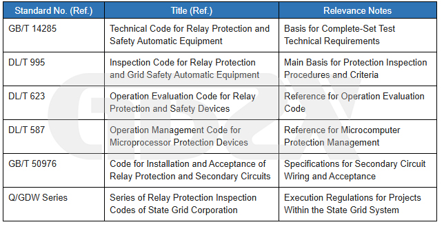
Reference Standards and Regulations (Use Current Valid Editions)
Disclaimer: The following standards are listed for reference only. Their scope of application, specific provisions, and current validity shall be verified against the latest valid texts published by the Standardization Administration of China, the National Energy Administration, and the relevant issuing authorities.
Written by an Industry Consultant Specializing in Integrated Protection Relay Testing, Secondary Circuit Commissioning, and Power Test Equipment Procurement (2025 Edition)
All references to standards are for informational purposes only. The latest valid editions shall prevail. Specific technical parameters shall comply with the equipment manual and applicable test procedures.


